Lateral mass fixation implant

a technology for fixing implants and lateral mass, which is applied in the field of lateral mass fixation implants, can solve the problems that the percutaneous approach cannot be used to insert screws into lateral mass of vertebrae, the drill can skid off the bone, and the pain of patients with posterior approaches is often persistent, so as to facilitate the insertion of the member

Inactive Publication Date: 2015-12-03
PROVIDENCE MEDICAL TECH
View PDF8 Cites 54 Cited by
  • Summary
  • Abstract
  • Description
  • Claims
  • Application Information

AI Technical Summary

Benefits of technology

[0007]The various embodiments described herein provide lateral mass and facet fixation implants, which may be inserted and applied via a posterior approach, using minimally invasive or less invasive techniques. The embodiments described below generally include an intrafacet implant (or “facet implant”) and a lateral mass fixation member attached to or attachable to the facet implant. The lateral mass fixation member can include one or more tabs extending from a middle portion and configured to secure the lateral mass fixation member to lateral masses of adjacent vertebrae. The tabs may be flexible, semi-rigid, or rigid, and may be collapsible to facilitate insertion of the member.

Problems solved by technology

Long-term patients with posterior approaches frequently have persistent pain due to the extensive nature of the dissection.
Starting a drill hole or inserting a screw into a lateral mass of a vertebra cannot currently be accomplished using a percutaneous approach.
This is because soft tissue gets caught up in the drill, and the drill can skid off the bone and go out of control.
Awls and firm pressure placed on bone with screws without direct visualization is dangerous in the posterior cervical spine, unless the surgeon has removed soft tissue and has direct visualization.

Method used


Image

  • Lateral mass fixation implant
  • Lateral mass fixation implant
  • Lateral mass fixation implant

Examples


Embodiment Construction

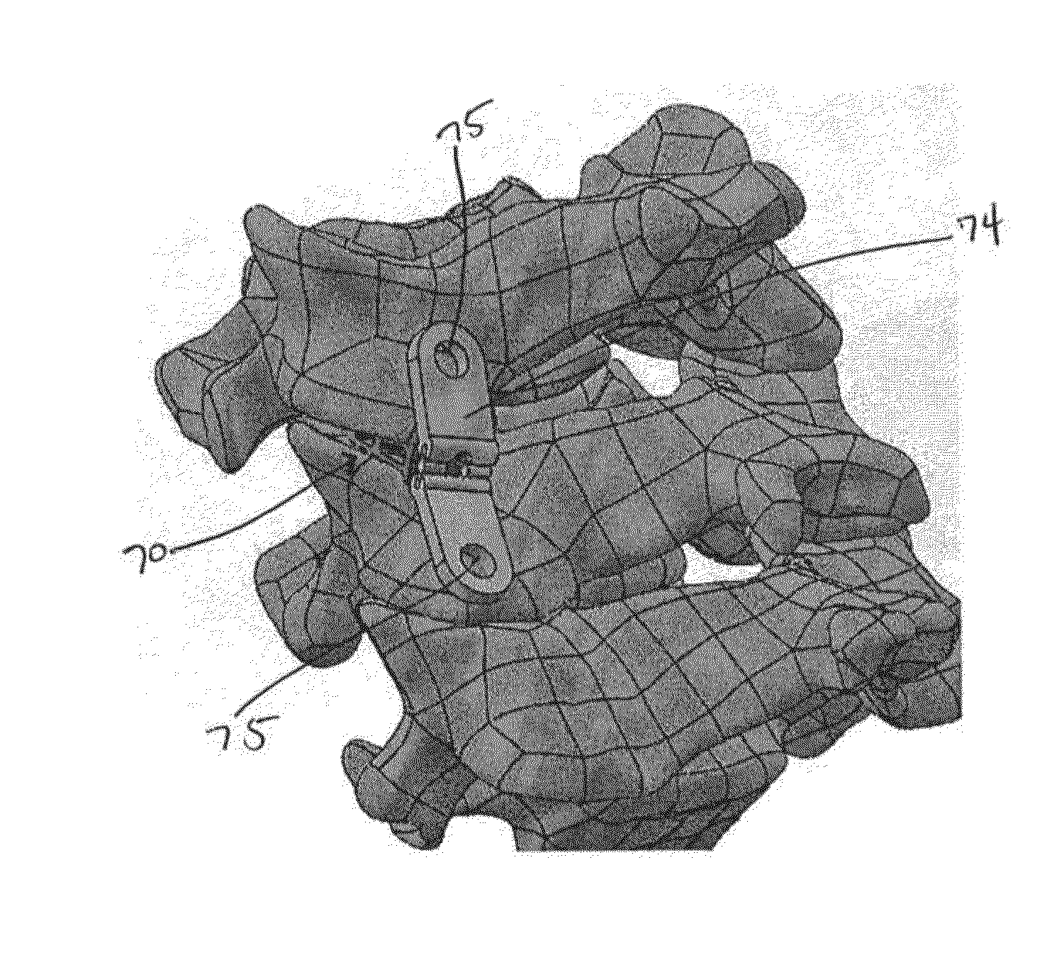
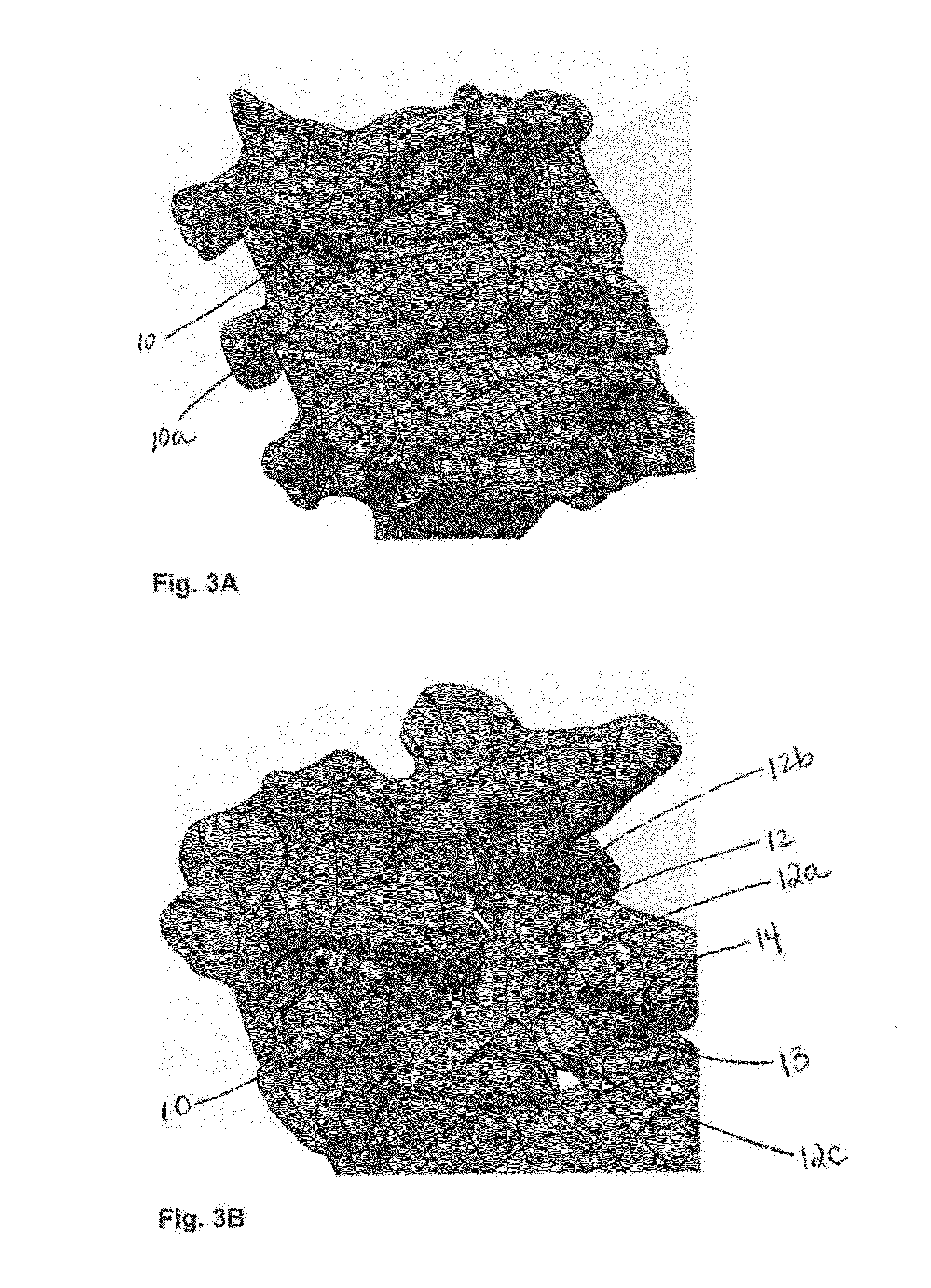
[0031]The various embodiments described herein include a system for providing lateral mass fixation in the cervical spine, using posterior access, less invasive or minimally invasive, insertion methods. Generally, each system includes a facet component and a lateral mass fixation component. In some embodiments, the facet component and the lateral mass fixation component are separate devices until they are attached in situ within the patient. In other embodiments, the facet and lateral mass fixation components may be combined into one device. Some embodiments may include simply a facet implant by itself, which may be attached to one or more lateral mass fixation devices or members. Similarly, a lateral mass fixation device or member may be provided by itself, and may be compatible with one or more facet implant devices. The embodiments described herein also include methods for inserting, implanting and attaching the facet components and lateral fixation components described herein.

[0...


PUM


Abstract

The various embodiments described herein provide lateral mass and facet fixation implants, which may be inserted and applied via a posterior approach, using minimally invasive or less invasive techniques. The embodiments described below generally include an intrafacet implant (or “facet implant”) and a lateral mass fixation member attached to or attachable to the facet implant. The lateral mass fixation member can include one or more tabs extending from a middle portion and configured to secure the lateral mass fixation member to lateral masses of adjacent vertebrae. The tabs may be flexible, semi-rigid, or rigid, and may be collapsible to facilitate insertion of the device. Methods for delivering the lateral mass and facet fixation implants are also described.

Description

CROSS-REFERENCE TO RELATED APPLICATIONS[0001]This application claims priority to U.S. Provisional Patent Application No. 62 / 003,443, entitled “Lateral Mass Fixation Implant,” filed on May 27, 2014. The full disclosure of the above-listed patent application is hereby incorporated by reference herein.BACKGROUND[0002]Posterior cervical fusion with lateral mass fixation is the most rigid cervical instrumentation. It requires extensive dissection of muscles and ligaments off the posterior spine, so that the surgeon can have direct visualization to safely perform the procedure. This dissection causes acute and chronic soft tissue pain syndrome. Acutely, patients are typically hospitalized for three to four days for pain control that requires IV narcotics. This is compared to one-day hospitalization for anterior approaches that do not require any muscle or soft tissue dissection. Long-term patients with posterior approaches frequently have persistent pain due to the extensive nature of the...

Claims


Application Information

Patent Timeline
Patent Type & Authority Applications(United States)
IPC IPC(8): A61B17/70
CPCA61B17/7064A61B2017/564A61B17/7035A61B17/7002A61B17/809A61B17/8085
Inventor MCCORMACK, BRUCE M.LIOU, EDWARDTANAKA, SHIGERUPHAN, CHRISTOPHER U.SMITH, JEFFREY D.SAUNDERS, TODD SHEPPARDSIEMIONOW, KRZYSZTOF
Owner PROVIDENCE MEDICAL TECH
Why Eureka
Try Eureka