Intravascular stent with regio-selective materials and structures

a regioselective material and stent technology, applied in the field of stents, can solve problems such as insufficient binding, and achieve the effects of improving the properties of specific locations, good deliverability, and high radial strength

Inactive Publication Date: 2015-12-03
NAT TAIWAN UNIV
View PDF1 Cites 6 Cited by
  • Summary
  • Abstract
  • Description
  • Claims
  • Application Information

AI Technical Summary

Benefits of technology

[0010]An object of the present invention is to provide a stent whose properties at specific locations are improved by adjusting the local composition of the stent materials, thereby providing a stent with high radial strength, good deliverability, high fracture toughness and fatigue resistance.

Problems solved by technology

In addition, the bar arms and the adjacent crowns each may independently contain other identical or compatible materials to avoid a large discrepancy in material properties between the bar arms and the adjacent crowns, which may result in insufficient binding.

Method used


Image

  • Intravascular stent with regio-selective materials and structures
  • Intravascular stent with regio-selective materials and structures
  • Intravascular stent with regio-selective materials and structures

Examples


example 1

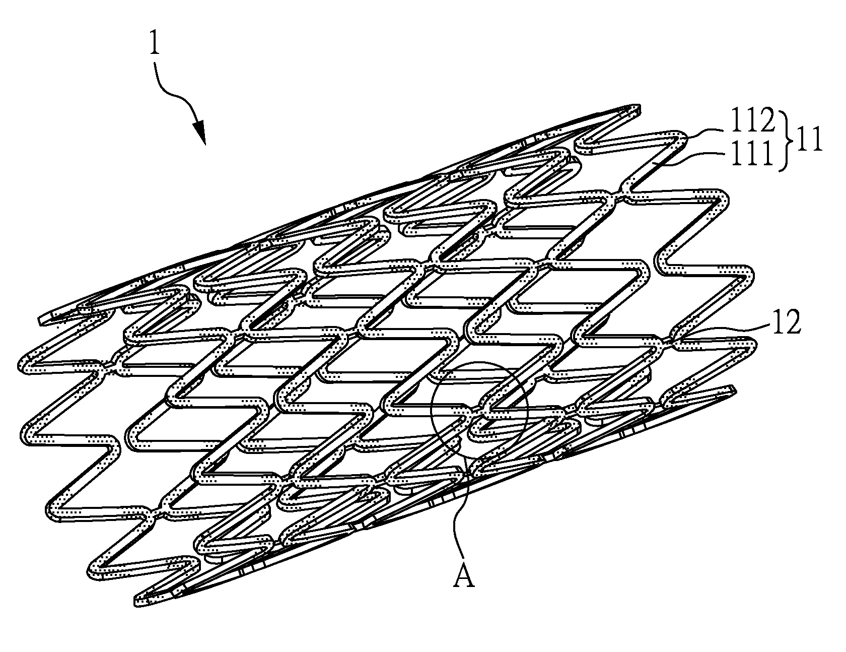
[0028]Please refer to FIGS. 1A and 1B, which illustrate a three-dimensional schematic drawing of the vascular stent 1 and an enlarged view of its part A according to Example 1 of the present invention. As shown in FIG. 1A, the stent 1 comprises: a plurality of radially-expandable rings 11 arranged along a longitudinal axis, wherein each of the radially-expandable rings 11 may include a plurality of bar arms 111 and a plurality of crowns 112, the adjacent crowns 112 being connected by the bar arms 111 therebetween, and a plurality of connectors 12 being disposed in between and connecting the radially-expandable rings 11. As shown in FIG. 1B, the bar arms 111 may include a first material, and the crowns 112 may include a second material which may be different from the first material. Furthermore, in this Example of the present invention, the connector 12 may be composed of a first material, a second material, or other materials, and the bar arms 111, the crowns 112, and the connector ...

example 2

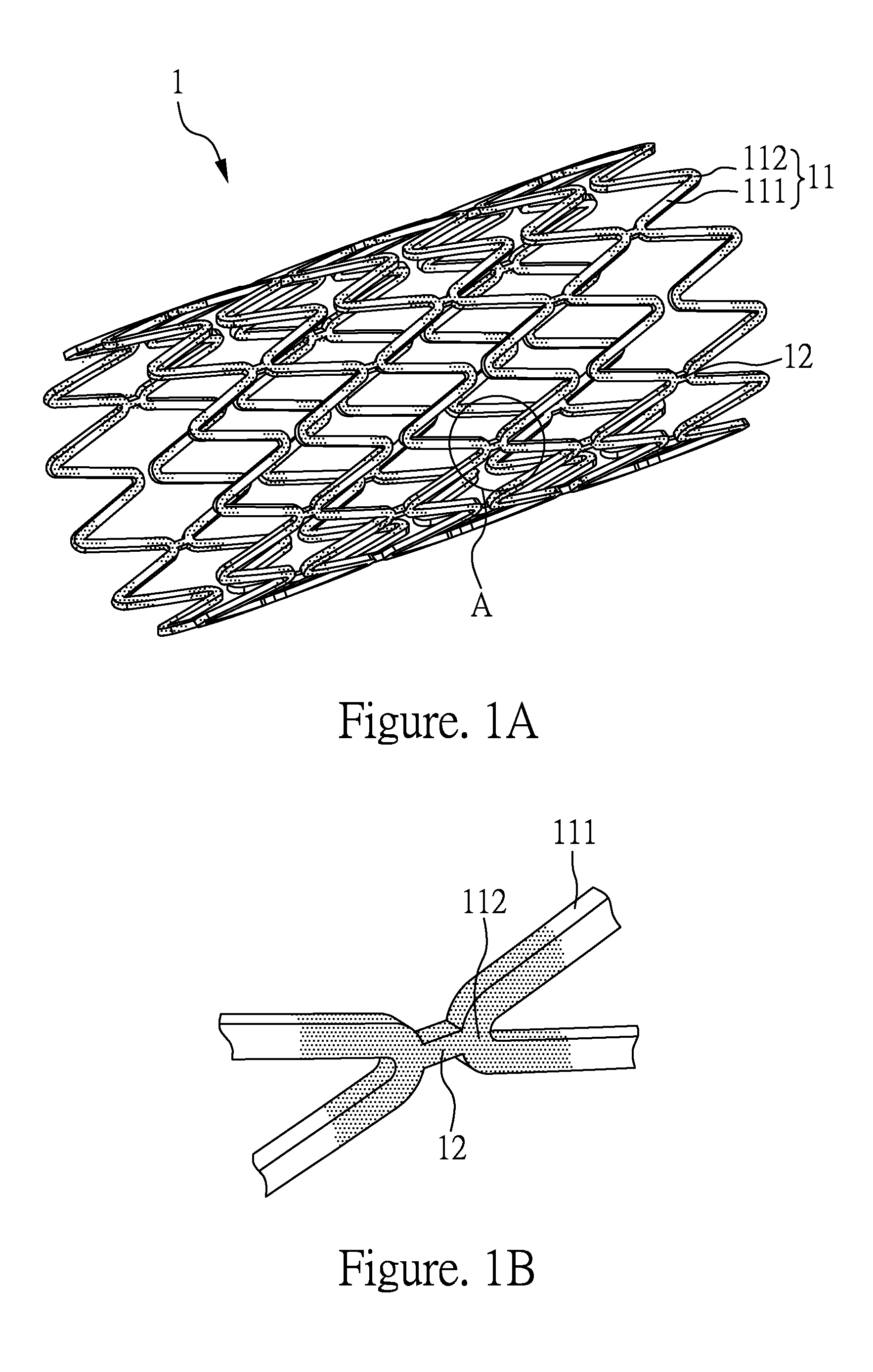
[0031]Please refer to FIGS. 2A and 2B, which illustrate a three-dimensional schematic drawing of the vascular stent 2 and an enlarged view of its part B according to Example 2 of the present invention. Example 2 and Example 1 are substantially the same, except that the connectors 22 of the stent 2 of Example 2 have a spring-like structure.

[0032]Therefore, as shown in FIG. 2A, the stent 2 comprises: a plurality of radially-expandable rings 21 arranged along a longitudinal axis, wherein each of the radially-expandable rings 21 may include a plurality of bar arms 211 and a plurality of crowns 212, the adjacent crowns 212 being connected by the bar arms 211 therebetween, and a plurality of connectors 22 being disposed in between and connecting the radially-expandable rings 21. As shown in FIG. 2B, the bar arms 211 may include a first material, and the crowns 212 may include a second material which may be different from the first material. Furthermore, in this embodiment of the present i...

example 3

[0034]Example 3 is substantially the same as Example 1, except that the material composition of the crowns and the bar arm has a graded distribution. Specifically, refer to FIG. 3, which is an enlarged partial view of the vascular stent 3 according to Example 3. As shown in FIG. 3, the bar arm 311 is made of the first material, and the crown 312 and the connector 32 are made of the second material, wherein the first material and the second material comprise bioresorbable polymer materials (e.g., poly(L-lactide) acid (PLLA), polyglycolic acid (PGA), polycaprolactone (PCL), poly(DL-lactide) acid (PDLLA), and polydioxanone (PDS)), and the weight ratio of the component B to the component A (B / A) from the center of the bar arm 311 to the center of the crown 312 has an incremental graded distribution.

[0035]Accordingly, by the graded distribution of the material composition ratio, this Example of the present invention not only improves the radial strength of the local position of the stent...


PUM

PropertyMeasurementUnit
weight ratioaaaaaaaaaa
weightaaaaaaaaaa

Abstract

The present invention relates to a stent, comprising: a plurality of radially-expandable rings arranged along a longitudinal axis, wherein each of the radially-expandable rings may include a plurality of bar arms and a plurality of crowns, the adjacent crowns being connected by the bar arms therebetween, and a plurality of connectors being disposed in between and connecting the radially-expandable rings, wherein the bar arms may include a first material, and the crowns may include a second material which may be different from the first material. Novel techniques for manufacturing a stent, such as 3D additive printing methods, could be used for realizing the disclosed stents.

Description

CROSS REFERENCE TO RELATED APPLICATION[0001]This application claims the benefits of Taiwan Patent Application Serial Number 103118364, filed on May 27, 2014, the subject matter of which is incorporated herein by reference.BACKGROUND OF THE INVENTION[0002]1. Field of the Invention[0003]The present invention relates to a stent, and especially to a stent with regio-selective materials and structures.[0004]2. Description of Related Art[0005]Vascular stenting has become one of the standard treatments for cardiovascular disease, and with the ever-changing medical technologies, a variety of stent-related inventions, such as drug-eluting stents, bioresorbable stents, and the like, are widely used for treating various cardiovascular diseases, such as coronary and peripheral artery diseases.[0006]For the clinical application of the vascular stent, important factors in stent design are deliverability, radial strength, flexibility, conformability, fracture toughness, and fatigue resistance. The...

Claims


Application Information

Patent Timeline
Patent Type & Authority Applications(United States)
IPC IPC(8): A61F2/90A61L31/06A61L31/02
CPCA61F2/90A61L31/022A61F2240/001B33Y80/00A61L31/06A61L31/14A61F2/915A61F2002/91558A61F2250/0014A61F2250/0015A61F2250/0019A61F2250/0029C08L67/04
Inventor HSIAO, HAO-MING
Owner NAT TAIWAN UNIV
Why Eureka
Try Eureka