
Autonomous vehicle, and object recognizing method in autonomous vehicle

a technology of autonomous vehicles and objects, applied in the direction of using reradiation, instruments, image enhancement, etc., can solve the problems of shifting between the travel control of the navigator and the actual travelling, deteriorating recognition accuracy, and inability to carry out high-speed processes, etc., to achieve high recognition accuracy and high speed

Active Publication Date: 2015-12-03
MURATA MASCH LTD
View PDF6 Cites 82 Cited by
  • Summary
  • Abstract
  • Description
  • Claims
  • Application Information

AI Technical Summary

Benefits of technology

The present invention provides a method for high-speed and accurate object recognition in autonomous vehicles. The method reduces the computation load and improves recognition accuracy by calculating the feature amount of an object within a specific search region based on the predicted position of the object. The method also reduces the number of matching candidate points by extracting feature points satisfying a specific geometric condition as the matching candidate points. In cases where some feature points are outside the search region, the search region is enlarged to improve the accuracy of object recognition. Overall, the method improves the efficiency and accuracy of object recognition in autonomous vehicles.

Problems solved by technology

If all the feature points in the image data are to be compared with the model data, high-speed process cannot be carried out.
If the number of feature points to be compared is reduced, on the other hand, the recognition accuracy deteriorates.
Furthermore, there may be a shift between the travel control of the navigator and the actual travelling.
Thus, a range for extracting the feature point needs to be widened to correctly recognize the position of the object in the image data, and as a result, the high-speed processing becomes difficult.

Method used


Image

  • Autonomous vehicle, and object recognizing method in autonomous vehicle
  • Autonomous vehicle, and object recognizing method in autonomous vehicle
  • Autonomous vehicle, and object recognizing method in autonomous vehicle

Examples


Embodiment Construction

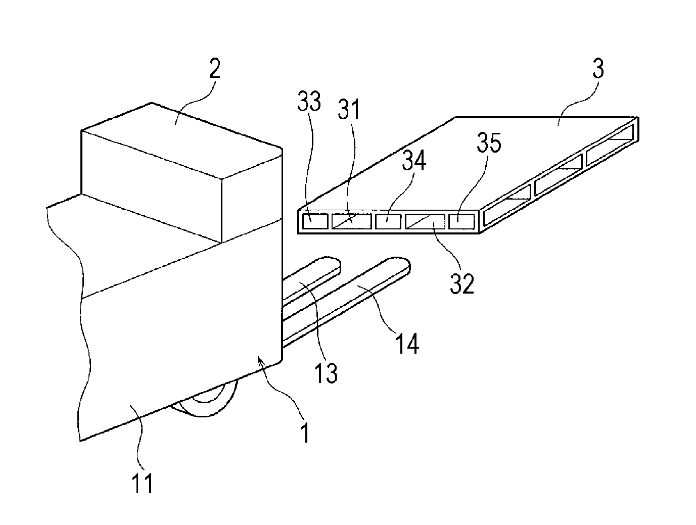
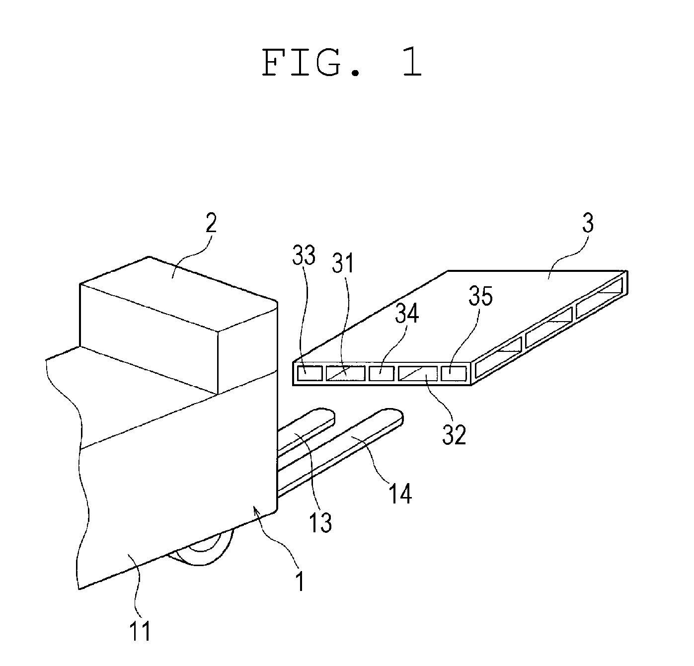
[0036]An unmanned forklift will be hereinafter described as an autonomous vehicle according to a first preferred embodiment of the present invention. FIG. 1 is an explanatory view of the unmanned forklift. An unmanned forklift 1 includes a controller (not illustrated) installed inside, and a main body 11 that can autonomously travel based on the control of the controller. The unmanned forklift 1 includes a pair of forks 13, 14 disposed in a rising and lowering manner at a front surface of the main body 11, and lifts up and transports a pallet 3. Furthermore, the main body 11 includes an object recognizing device 2. The object recognizing device 2 includes a camera, which camera at least acquires image information of a front side of the main body 11. The object recognizing device 2 recognizes the pallet 3 to be recognized from a three-dimensional image based on the image information.

[0037]As illustrated in FIG. 1, for example, the pallet 3 includes inserting ports 31, 32 to which the...


PUM


Abstract

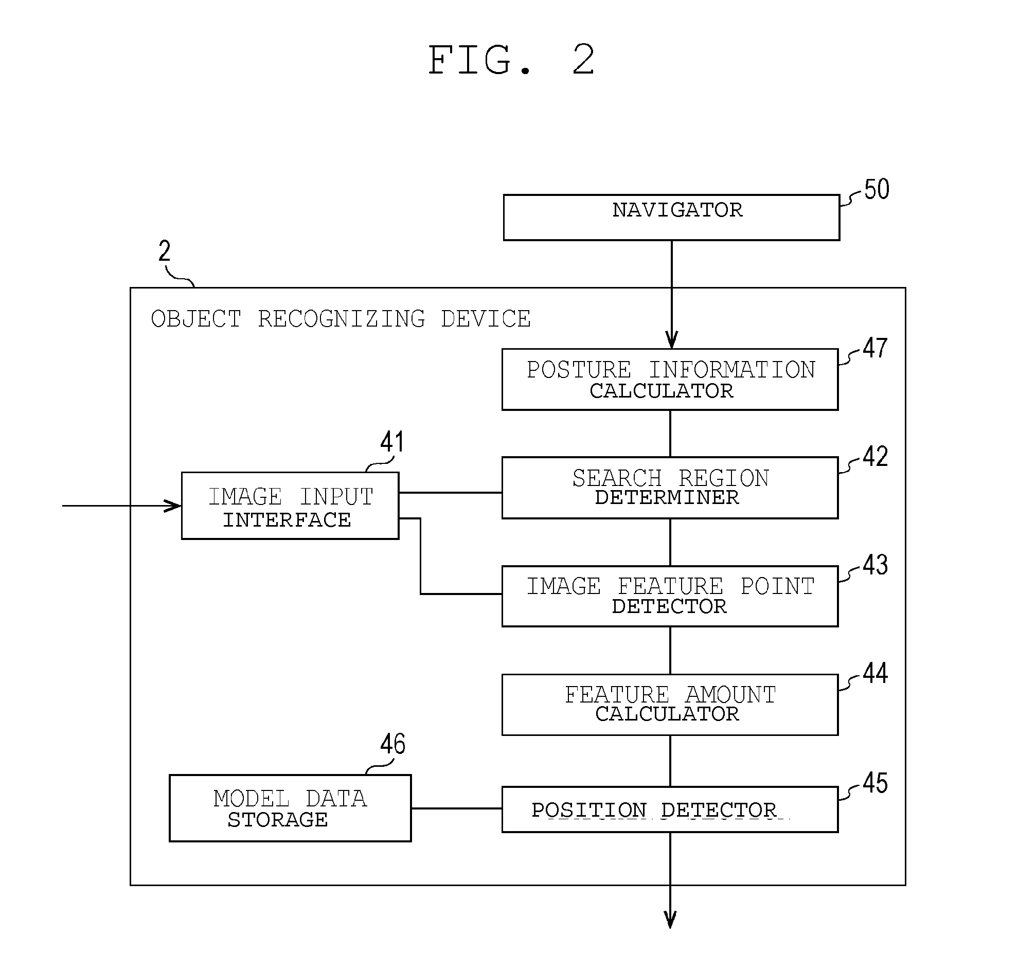
An autonomous vehicle includes a travel vehicle main body, a model data storage, a photographic device, a search region determiner, an image feature point detector, a feature amount calculator and a position detector. The travel vehicle main body autonomously travels to a target position. The model data storage stores model data related to a geometric feature of an object. The photographic device photographs a periphery of the travel vehicle main body at the target position to acquire image data. The search region determiner predicts a position of the object based on the image data, and determines a search region of a predetermined range including the predicted position of the object. The image feature point detector detects a feature point of the image data with respect to the search region. The feature amount calculator calculates a feature amount of a matching candidate point extracted from the feature point. The position detector matches the feature amount of the matching candidate point with the model data to recognize the position of the object based on the image data.

Description

CROSS-REFERENCE TO RELATED APPLICATIONS[0001]This application claims priority under 35 U.S.C. 119 to Japanese Patent Application No. 2014-109258, filed on May 27, 2014, which application is hereby incorporated by reference in its entirety.BACKGROUND OF THE INVENTION[0002]1. Field of the Invention[0003]The present invention relates to an autonomous vehicle, and an object recognizing method in the autonomous vehicle.[0004]2. Description of the Related Art[0005]An autonomous vehicle that autonomously moves in an environment needs to recognize a position of an object, a direction in which the object is located, and the like in order to realize a mutual action with the object existing in surrounding environments. For example, an unmanned forklift that automatically transports an object, such as a pallet, which is a target, includes a navigator, a camera, and an object recognizing device. The navigator performs a travel control along a path. The camera captures images of the periphery of ...

Claims


Application Information

Patent Timeline
IPC IPC(8): G06K9/00H04N13/02G06T7/00G06K9/46G06K9/60G01S17/86G01S17/894H04N13/239
CPCG06K9/00577G06K9/00523G06K9/4604G06K9/60G06T7/0075G06T2207/10012G06K9/4647G06T7/0081G06K9/00201H04N13/0203G06T7/0042G05D1/0246G05D1/0225G01B11/24B66F9/063G01S7/4808G01S7/4802G06T7/73G06T7/593G06T7/11H04N13/239G01S17/86G01S17/894H04N13/271G06V20/653H04N13/204G06V20/64G06V20/80G06F2218/08
Inventor IIDA, MASAOMI
Owner MURATA MASCH LTD
Learn More