Eureka AIR delivers breakthrough ideas for toughest innovation challenges, trusted by R&D personnel around the world.

Power converter controlling method

a power converter and control method technology, applied in the direction of electric variable regulation, process and machine control, instruments, etc., can solve the problems of high switching loss, two kinds of power loss in and very low power efficiency of the power converter using pwm control

Inactive Publication Date: 2015-12-03
DELTA ELECTRONICS SHANGHAI CO LTD
View PDF4 Cites 6 Cited by
  • Summary
  • Abstract
  • Description
  • Claims
  • Application Information

AI Technical Summary

Benefits of technology

This disclosure provides a method for controlling a power converter that produces power for a load. The method involves detecting the power output and adjusting the switch's frequency of operation accordingly. If the power is too high for the load, the power converter operates in a different mode to adjust the switch's frequency. If the power is too low, the power converter operates in a burst mode and the switch's frequency is fixed at a predetermined value. This method helps to ensure the power converter operates efficiently and produces the desired output for the load.

Problems solved by technology

When the load is light (low power consumption), power efficiency of the power converter using PWM control is very low.
There are two kinds of power loss in the power converter using PWM control.
However, the switching frequency of the power converter using PWM control in a condition of the light load is exactly equal to that in a condition of a heavy load, and therefore the switching loss is higher.
That is the disadvantage of power converter using PWM control.
At this time, a switching operation of the switching unit will generate an audio noise, and a user may hear an annoying high frequency noise continuously.

Method used


Image

  • Power converter controlling method
  • Power converter controlling method
  • Power converter controlling method

Examples


Embodiment Construction

[0020]Specific embodiments of the present disclosure are further described in detail below with reference to the accompanying drawings, however, the embodiments described are not intended to limit the present disclosure and it is not intended for the description of operation to limit the order of implementation. Moreover, any device with equivalent functions that is produced from a structure formed by a recombination of elements shall fall within the scope of the present disclosure. Additionally, the drawings are only illustrative and are not drawn to actual size.

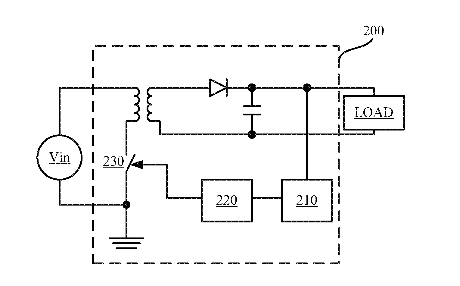
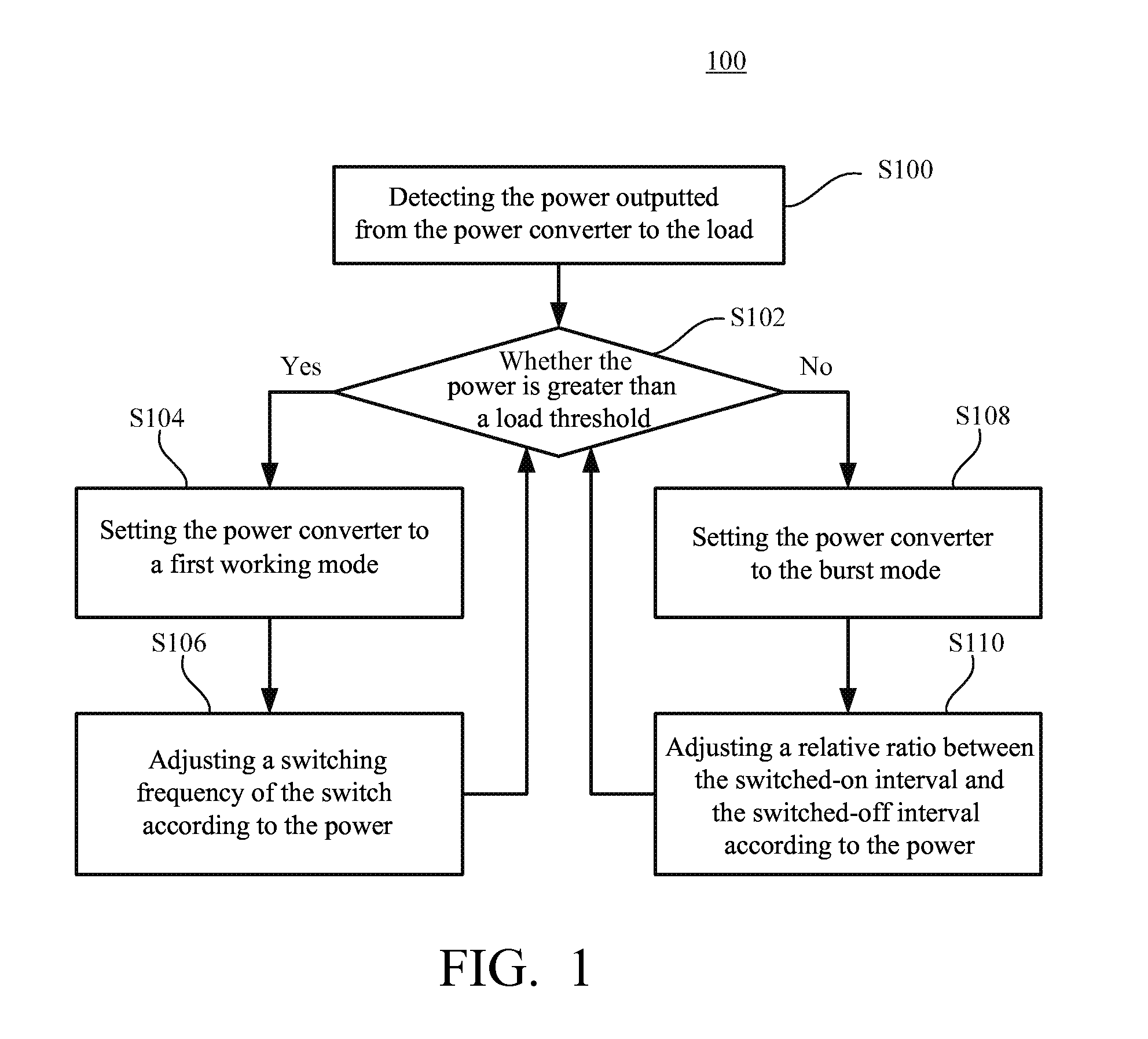
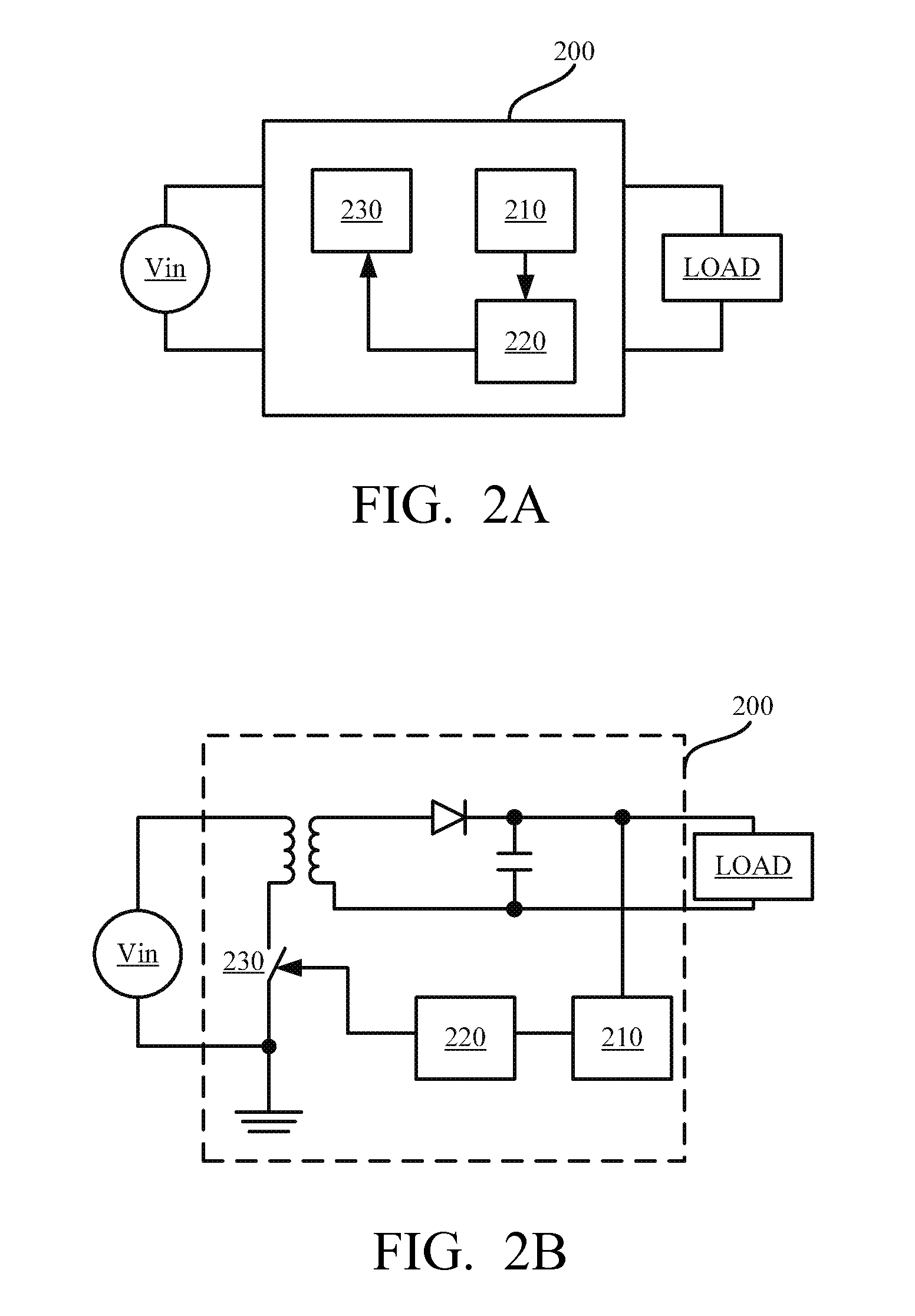
[0021]Referring to FIG. 1 and FIG. 2A, FIG. 1 is a flow chart of a power converter controlling method 100 in an embodiment of the disclosure. In the present embodiment, a power converter controlling method 100 is used in a power converter. The power converter may be applied in a switching mode power supply. FIG. 2A is a schematic diagram illustrating a power converter 200 used by the power converter controlling method 100 a...


PUM


Abstract

A power converter controlling method suitable for a power converter is disclosed. The power converter is configured to output a power to a load. The power converter includes a switch. The power converter controlling method includes the following steps. The power outputted from the power converter to the load is detected and a switching frequency of the switch is adjusted according to the power. When the power is greater than a load threshold, the power converter is set to a first working mode, and the switching frequency of the switch is adjusted according to the power in the first working mode. On the other hand, when the power is smaller than or equal to the load threshold, the power converter is set to a burst mode, and the switching frequency is fixed at a setting frequency value in the burst mode.

Description

RELATED APPLICATIONS[0001]This application claims the priority benefit of China Application Serial Number 201410228971.1, filed May 27, 2014, which is herein incorporated by reference.BACKGROUND[0002]1. Field of Invention[0003]The present invention relates to a power converter. More particularly, the present invention relates to a method for controlling a power converter.[0004]2. Description of Related Art[0005]The power converter generally consists of a switch unit, an inductor, a capacitor circuit, and a controlling circuit. The controlling circuit generates a series of control signals to turn on or to turn off the switch unit so that the switch unit outputs a pulse current. The inductor and the capacitor circuit act as a low pass filter, which is utilized to convert the pulse current into a direct current. The direct current is provided to a load.[0006]Generally, there are two common approaches for the controlling circuit. The one adopts a fixed switching frequency and changing a...

Claims


Application Information

Patent Timeline
Patent Type & Authority Applications(United States)
IPC IPC(8): H02M3/24
CPCH02M3/24H02M3/156H02M3/33507H02M3/3376Y02B70/10H02M1/0035H02M1/0054H02M1/0058
Inventor WEI, DONGJIAO, DE-ZHIXU, DAO-FEI
Owner DELTA ELECTRONICS SHANGHAI CO LTD
Why Eureka
Eureka Blog
Learn More