Doherty power amplifier apparatus

Active Publication Date: 2015-12-03
ZTE CORP
View PDF3 Cites 3 Cited by
  • Summary
  • Abstract
  • Description
  • Claims
  • Application Information

AI Technical Summary

Benefits of technology

[0021]As compared to the related art, the present invention has the following advantages:
[0022]the consistency and manufacturability of batch manufacture of power amplifiers are good. Manufacture consistency is the biggest bottleneck restricting the batch delivery of the Doherty power amplifiers, currently, some manufacturers ensure large batch delivery at the cost of efficiency and linearity parameters or expensive costs, and in the present invention, this problem can be solved by regulating the power of the power amplifier with inventive zero cost.
[0023]The efficiency is high. The present invention solves the problem of reduced efficie

Problems solved by technology

The conventional Doherty power amplifier has a relatively big disadvantage, i.e. due to the discretion of the input standing waves of the power amplifier device during the batch manufacture of the power amplifier, the consistency of the output of the power splitter (S in the figure) is affected, which will cause the mismatching when combining the output powers of the carrier amplificat

Method used


Image

  • Doherty power amplifier apparatus
  • Doherty power amplifier apparatus
  • Doherty power amplifier apparatus

Examples


embodiment 1

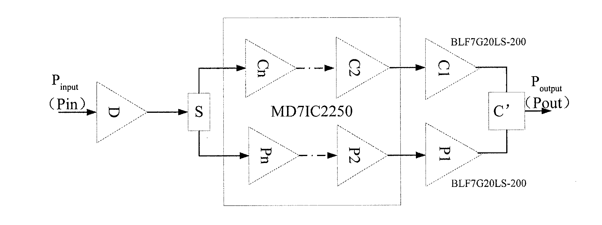
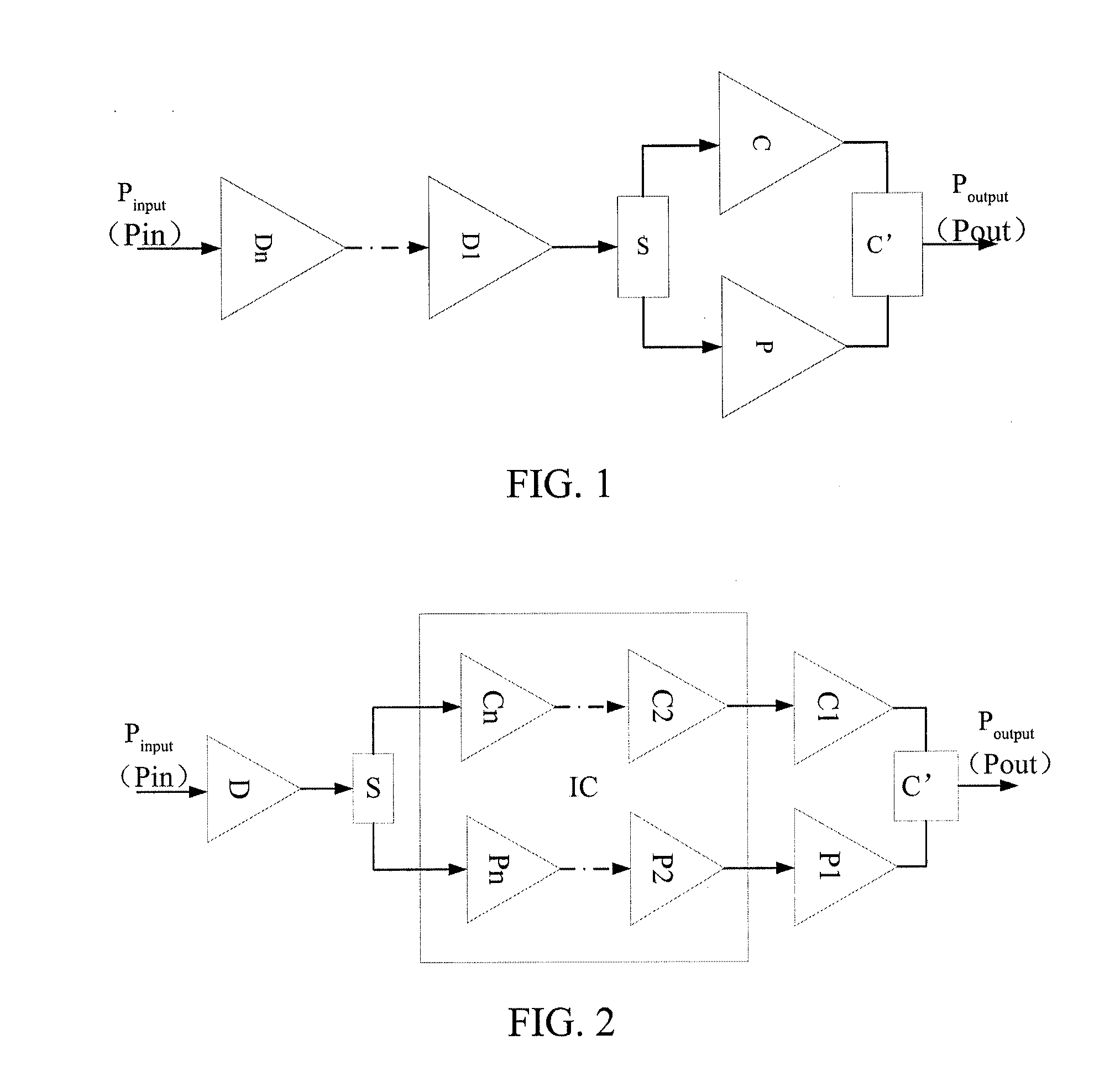
[0046]The technical solution of the present invention applied in a duplex Doherty architecture is as shown in FIG. 2. In FIG. 2, Pin is the input signal port, D is the drive amplifier circuit, S is the power splitter, C1 to Cn form a carrier amplification branch of a multi-stage Doherty power amplifier, P1 to Pn form a peak amplification branch of the multi-stage Doherty power amplifier, and C′ is the power combiner.

[0047]When the input signal is small, the whole peak amplification branch is in the cutoff state, and the whole carrier amplification branch works in class AB matching the maximum efficiency; when the input signal increases to a certain extent, the carrier amplification branch gradually transits from the amplification area to the saturation area, and the peak amplification branch gradually transits from the cutoff area to the amplification area; and with the increasing of the input signal, the whole carrier amplification branch and peak amplification branch finally work ...

embodiment 2

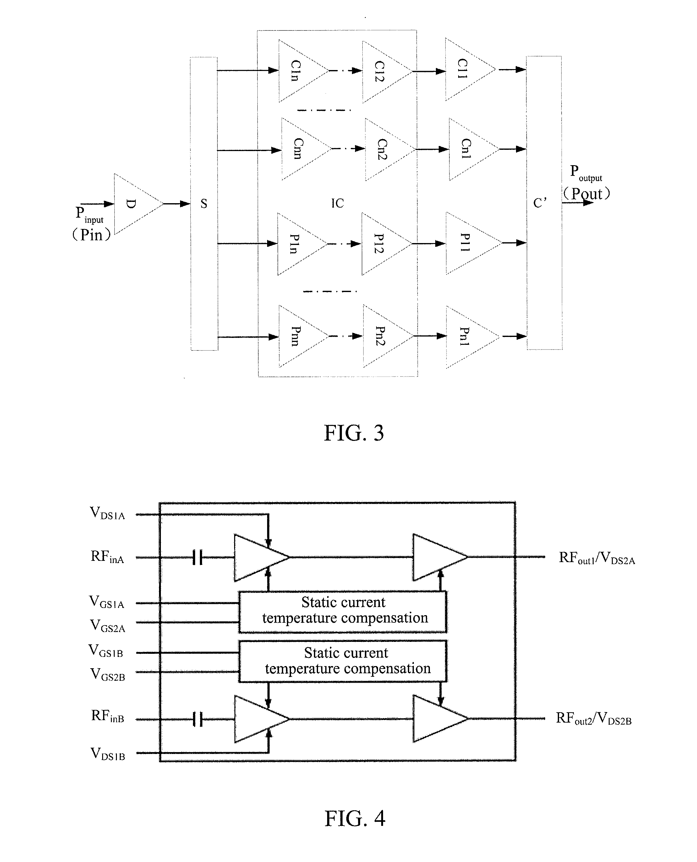
[0050]The technical solution of the present invention applied in a multiplex Doherty architecture is as shown in FIG. 3. In the figure, Pin is the input signal port, D is the drive amplifier circuit, S is the power splitter, C11 . . . C1n and Cn1 . . . Cnn form the first to the nth carrier amplification branches of a multi-stage Doherty power amplifier, P11 . . . P1n and Pn1 . . . Pnn form the first to the nth peak amplification branch of the multi-stage Doherty power amplifier, and C′ is the power combiner. The principle of improving its performance is similar to that of duplex multi-stage Doherty architecture.

[0051]All the drive stage amplifiers in the present invention can be designed into one piece of IC (integrated circuit), and embody excellent advantages regarding the aspects such as performance index and manufacturability of the power amplifier.

[0052]Hereinafter, the embodiments applying the power amplifier of the present invention will be set forth.

[0053]The main technical ...


PUM


Abstract

Disclosed is a Doherty power amplifier apparatus, including: a drive amplifier circuit, a power splitter circuit and a power combiner circuit, wherein the power splittercircuit is connected to the drive amplifier circuit, the apparatus further comprising: a carrier amplifier circuit and a peak amplifier circuit connected in parallel between the power splitter circuit and the power combiner circuit, wherein the carrier amplifier circuit comprises one or more parallel carrier amplification branches, wherein each carrier amplification branch comprises a multi-stage carrier amplifier apparatus, the multi-stage carrier amplifier apparatus is used for achieving multi-stage carrier amplification; and the peak amplifier circuit comprises one or more parallel peak amplification branches, wherein each peak amplification branch comprises a multi-stage peak amplifier apparatus, the multi-stage peak amplifier apparatus is used for achieving multi-stage peak amplification.

Description

TECHNICAL FIELD[0001]The present invention relates to the communication field, and particularly, to a multi-stage Doherty power amplifier apparatus.BACKGROUND OF THE RELATED ART[0002]With the promotion of the concepts of greenery and low-carbon economy being popular in the world, the operators requires more and more to lower the power consumption of the wireless communication system. In the wireless communication system, the radio frequency power amplifier (abbreviated as power amplifier) in the base station device is one of the core modules of the whole system, and an important parameter of the radio frequency power amplifier is power amplifier efficiency. Data analysis indicates that in the whole base station device, the power consumption of the power amplifier portion occupies about 60% of the whole power consumption, thus, improving the efficiency of the power amplifier is the most effective means to reduce the power consumption of the base station device and reduce the operatin...

Claims


Application Information

Patent Timeline
IPC IPC(8): H03F1/02H03F3/21H03F3/19
CPCH03F1/0288H03F3/19H03F2203/21106H03F2200/451H03F3/211H03F1/0261H03F3/245H03F2200/15H03F2200/18H03F2200/405H03F2200/447
Inventor CHEN, HUAZHANGLIU, JIANLIAN, JINYUANCUI, XIAOJUN
Owner ZTE CORP
Why Eureka
Try Eureka