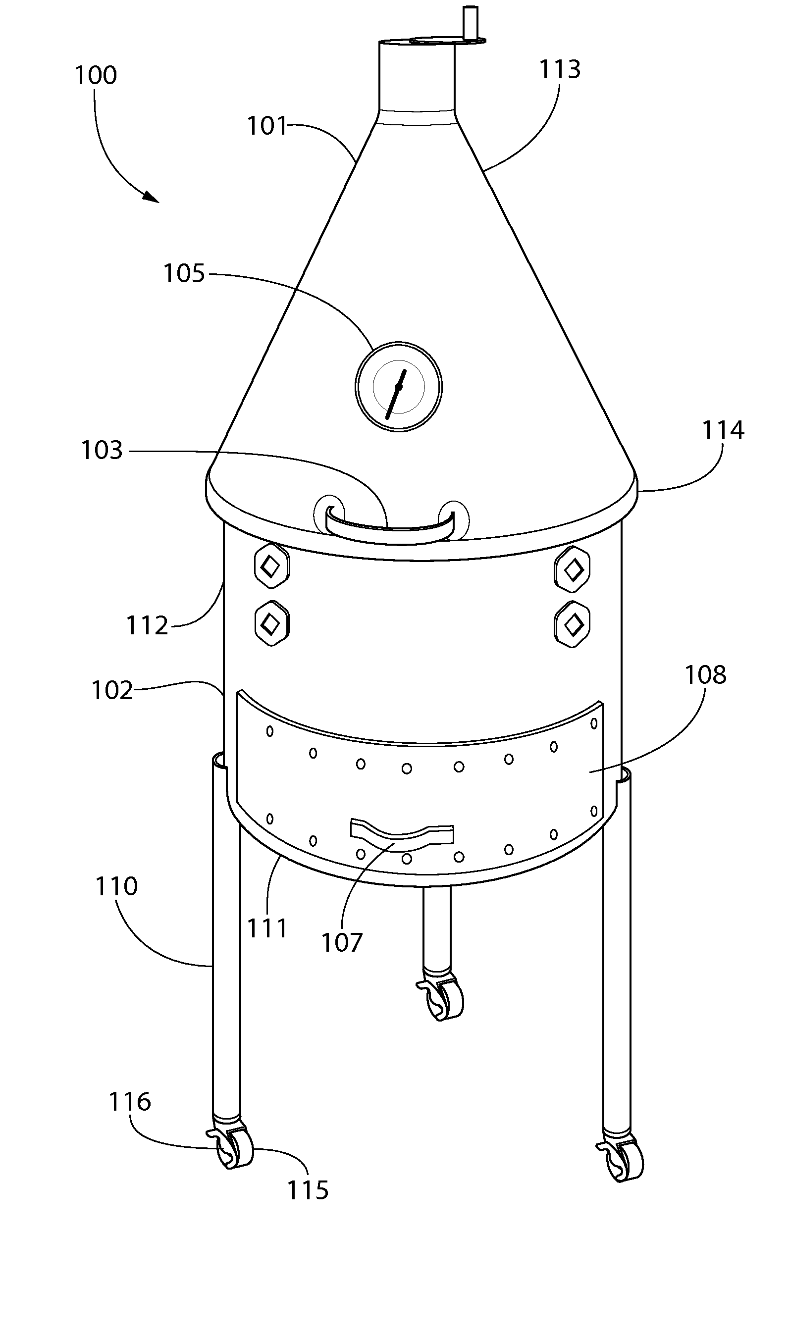
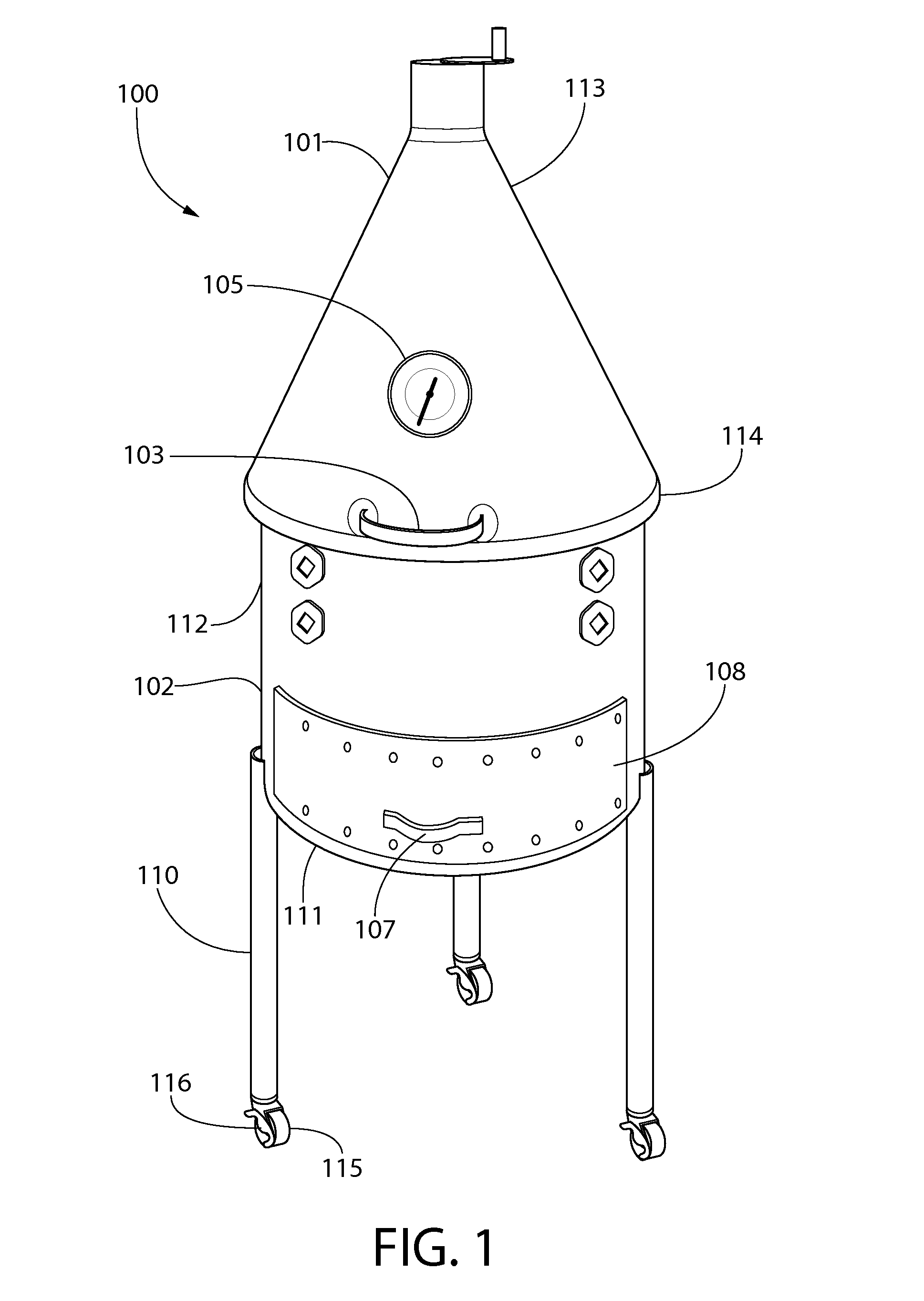
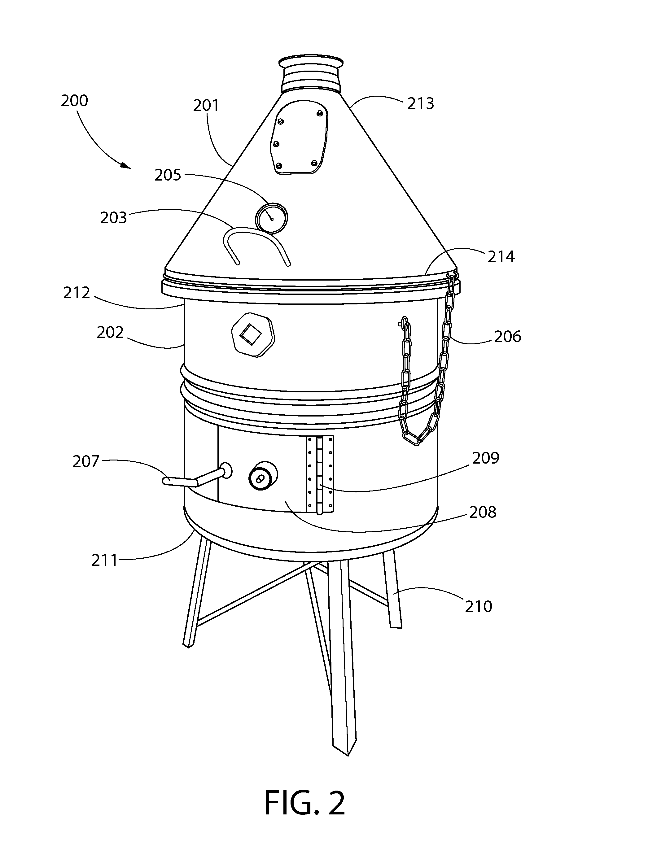
[0026]The present invention is directed towards a barbecue grill. For purposes of clarity, and not by way of limitation, illustrative views of the present barbecue grill are described with references made to the above-identified figures. Various modifications obvious to one skilled in the art are deemed to be within the spirit and scope of the present invention.
[0027]As used in this application, the word “exemplary” is used herein to mean serving as an example, instance, or illustration. Any aspect or design described herein as “exemplary” is not necessarily to be construed as preferred or advantageous over other aspects or designs. Rather, use of the word exemplary is intended to disclose concepts in a concrete fashion. As used in this application, the term “or” is intended to mean an inclusive “or” rather than an exclusive “or.” Additionally, the articles “a” and “an” as used in this application and the appended claims should generally be construed to mean “one or more” or “at least one” unless specified otherwise or clear from context to be directed to a singular form.
[0028]Referring now to FIGS. 1 through 3, there are shown views of exemplary embodiments of the present invention. The present invention comprises a barbecue grill 100, 200. The barbecue grill 100, 200 includes a housing member 102, 202 having a substantially cylindrical shape with a defined interior volume. The interior volume of the housing member 102, 202 is adapted to hold fuel source therein, as well as a grill grate for cooking food thereon. The fuel source can be inserted into the housing member 102 via a fuel source compartment 108, which can open and close via a handle 107. Alternatively, the fuel source can be inserted into the housing member 202 via an opening, which is accessible through a door 208 and a handle 207 attached thereto, wherein the door 208 is attached to the housing member 202 via hinges 209.
[0029]The housing member 102, 202 includes an open upper end 112, 212 and a closed lower end 111, 211. The diameter of the cross section of the housing member 102, 202 is uniform over its length, wherein the length of the housing member 102, 202 is defined as the distance between the upper end 112, 212 to the lower end 111, 211 thereof. In this regard, the housing member 102, 202 is not tapered.
[0030]The upper end 112 of the housing member 102 comprises a substantially cone-shaped or funnel-shaped hood 101 attached thereto via hinges 121. Alternatively, the hood 201 may be attached to the housing member 202 via a chain 206. The hood 101, 201 comprises an open lower end 114, 214 and an open upper end 113, 213. The distance between the lower end 114, 214 and the upper end 113, 213 of the hood 101, 201 defines the length thereof. The cross section of the hood 101, 201 is substantially circular in shape. The diameter of the cross section of the hood 101, 201 decreases from the lower end 114, 214 to the upper end 113, 213 thereof such that the hood 101, 201 resembles an inverted cone when viewed from the front, side, or the back.
[0031]The lower end 114, 214 of the hood 101, 201 directly contacts the upper end 112, 212 of the housing member 102, 202 when the grill 100, 200 is in a closed position. In this way, the diameter of the lower end 114, 214 of the hood 101, 201 is substantially equal to the diameter of the cross section of the upper end 112, 212 of the housing member 102, 202. In some embodiments, each of the upper end 112, 212 of the housing member 102, 202 and the lower end 114, 214 of the hood 101, 201 comprises a lip therearound so as to create a complete seal when the grill 100, 200 is in the closed position.
[0032]In operation, a user can open and close the hood 101, 201 via a handle 103, 203 attached thereto. In the closed position, the cone-shaped hood 101, 201 circulates heat similarly to a convection oven. In this way, the heated air within the interior volume of the housing member 102, 202 and the hood 101, 201 can rotate around the food while it is being cooked on top of the grill grate. It is contemplated that the entire grill 100, 200 is composed of stainless steel or other types of suitable, durable material that can withstand weather and outside elements to prolong the use thereof without rusting and/or corroding.
[0033]The hood 101, 201 further includes a thermometer 105, 205 for measuring the temperature of the interior volume of the housing member 102, 202. In this way, the user can determine whether the temperature of the interior volume of the housing member 102, 202 is the desired cooking temperature without opening the hood 101, 201 and utilizing another thermometer. It is contemplated that the thermometer 105, 205 comprises a cooking thermometer or a kitchen thermometer and that the thermometer can withstand excessive heat.
[0034]The lower end 111 of the housing member 102 comprises a plurality of legs 110 attached thereto, wherein each of the legs 110 comprises a caster wheel 115 with a lock 116 thereon. In this way, the grill 100 can be moved to different locations in a convenient manner and the user need not pick up the grill in order to transport it. In the illustrated embodiment, the housing member 102 is attached to three adjustable legs 110, wherein the legs 110 form a triangle configuration or a tripod configuration. In other embodiments, however, the present invention may comprise fewer or more than three adjustable legs.
[0035]It is contemplated that in some embodiments, the legs 117 may be adjustable in length, wherein the length of each of the legs 117 is defined as the distance between the upper end 118 of the leg 117 and the lower end 119 of the leg 117. The legs 117 may be telescopic in construction so that they can expand or retract. Additionally, each of the legs 117 may comprise a lock for securing the legs 117 at a desired length. In the illustrated embodiment, the lock comprises a fastener 120 for securing the legs 117 in place.
[0036]Referring now to FIG. 4 there is shown a close up view of the damper 104 of the present invention. The upper end 113 of the hood 101 includes a tubular portion 122 extending upward therefrom. The tubular portion 122 comprises a circular cross section having a diameter that is uniform over its length. Because the upper end 123 of the tubular portion 122 is open and does not come to a point, it is important to prevent moisture or debris from entering the interior volume of the housing member while providing air vent.
[0037]The upper end 123 of the tubular portion 122 includes a damper 104 attached thereto. The damper 104 comprises a circular plate that includes an upper surface that is coextensive with a lower surface. The upper surface includes a handle or a knob 124 extending upward therefrom. The damper 104 is attached to the upper end 123 of the tubular portion 122 via a fastener 125 so that it can slide into an open position and a closed position. The diameter of the plate of the damper 104 is substantially equal to or greater than the diameter of the cross section of the tubular portion 122 so that it that prevents rain or other elements from entering into the hood 101 and the interior volume of the housing member.
[0038]Referring now to FIG. 5, there is shown a close up view of the draft/temperature control 126 of the present invention. In the illustrated embodiment, the draft/temperature control 126 includes a rectangular opening 127 having a top edge and a bottom edge. Each of the top and bottom edges includes a plate 128 attached thereto, such that a portion of the plate is positioned over the opening 127 and another portion of the plate is positioned over the housing member 102. The plates 128 may be welded to the housing member 102 so that they are substantially unitary in structure. Each of the plates 128 creates a channel between the underside of the plate 128 and the opening 127. The plates 128 are parallel to each other and are spaced apart so as to create a gap and leave part of the opening 127 exposed.
[0039]Disposed between the plates 128 is a door 129 having a handle or a knob 130 extending outward therefrom. In the illustrated embodiment, the handle 130 is biased toward one end of the door 129. The door 129 is shaped and dimensioned to fit between the plates 128 and slide within the channels so that it can completely cover the opening 127 in a closed position and then slide sideways to an open position. The door 129 can also be slid to the side slightly so that it is opened only partially.
[0040]By controlling the size of the opening 127, the user can control the airflow to and from the exterior and interior of the grill. Controlling the airflow helps regulate the climate of the interior volume of the housing member 102. More specifically, increasing the size of the opening 127 helps decrease the temperature within the interior volume of the housing member 102 by allowing hot air to escape. Conversely, decreasing the size of the opening 127 helps increase the temperature within the interior volume of the housing member 102 by retaining hot air therein.
[0041]Referring now to FIG. 6, there is shown a close up view of the hinges 121 of the present invention. Preferably, the hinges 121 comprise a first section 134 attached to a second section 135. The first section 134 comprises a C-shape having an upper end 136 and a lower end 137, wherein the lower end 137 is attached to the housing member 102. The second section 135 is attached to the hood 102 and hingedly connects to the upper end 136 of the first section 134. In another embodiment, the first section 134 of the hinges 121 comprises a D-shape having a vertical portion 138 in addition to the C-shaped portion, wherein the vertical portion 138 is attached to the housing member 102 and the upper end 136 of the curved portion is attached to the second section 135.
[0042]Referring now to FIG. 7, there is shown a view of the interior of the present invention. The interior volume 139 of the housing member 102 comprises a grill grate 133 that is biased toward the upper end 112 thereof, wherein the upper end 112 comprises a lip 140 therearound. The grill grate 133 comprises a substantially circular shape with a plurality of openings 141 disposed thereon. In the illustrated embodiment, the openings 141 comprise a circular shape. In other embodiments, however, the openings may comprise various shapes and sizes.
[0043]The perimeter of the grill grate 133 rests on top of a plurality of pegs or support members disposed on the interior wall of the housing member. The pegs protrude perpendicularly inward and are spaced apart at regular intervals. The illustrated embodiment includes a first and second sets of pegs 131, 132 wherein the first set 131 is closer to the upper end 112 of the housing member 102 than the second set 132 so that the first set 131 is higher in elevation than the second set 132. Additionally, the pegs in the first set of pegs 131 are level with each other. Similarly, the pegs in the second set of pegs 132 are level with each other. In this way, the grill grate 133 remains level or substantially parallel to the ground, preventing food from sliding off of the grill grate 133.
[0044]The grill grate 133 can be placed on the first set of pegs 131 or the second set of pegs 132. When the grill grate 133 is placed on the first set of pegs 131, it is further away from the fuel source than when the grill grate 133 is placed on the second set of pegs 132. Thus, the cooking temperature is lower when the grill grate 133 is placed on the first set of pegs 131 than when it is on the second set of pegs 132.
[0045]Referring now to FIGS. 8 and 9, there are shown views of the fuel source compartment 108 of the present invention. The fuel source compartment 108 is biased toward the lower end 111 of the housing member 102 and functions similarly to a drawer. In this regard the compartment 108 includes a bottom wall having a front wall 142, back walls 143, and side walls 144 extending upward therefrom, defining an interior volume therein and leaving the top open. The front wall 142 is curved to follow the contours of the housing member 102, and includes a handle 107 thereon.
[0046]The interior volume of the compartment 108 includes a plurality of rods 145 extending from the front wall 142 to the back walls 143. The rods 145 are spaced apart at regular intervals and are parallel with one another. The rods 145 are configured to support a fuel source thereon while allowing the ashes or other debris to fall therebetween.
[0047]The compartment 108 can extend outward from the housing member 102 and retract into the housing member 102 through an opening 146 disposed thereon. The front wall 142 of the compartment 108 is dimensioned so that it extends beyond the perimeter of the opening so as to completely cover the opening 146 when in a closed position. The accessibility of the compartment 108 from the exterior of the housing member 102 eliminates the need to remove the grill grate from the upper end 112 of the housing member 102 when adding fuel. Thus, the present invention increases convenience when adding fuel while cooking.
[0048]It is therefore submitted that the instant invention has been shown and described in what is considered to be the most practical and preferred embodiments. It is recognized, however, that departures may be made within the scope of the invention and that obvious modifications will occur to a person skilled in the art. With respect to the above description then, it is to be realized that the optimum dimensional relationships for the parts of the invention, to include variations in size, materials, shape, form, function and manner of operation, assembly and use, are deemed readily apparent and obvious to one skilled in the art, and all equivalent relationships to those illustrated in the drawings and described in the specification are intended to be encompassed by the present invention.
[0049]Therefore, the foregoing is considered as illustrative only of the principles of the invention. Further, since numerous modifications and changes will readily occur to those skilled in the art, it is not desired to limit the invention to the exact construction and operation shown and described, and accordingly, all suitable modifications and equivalents may be resorted to, falling within the scope of the invention.