
Real time ultrasound thermal dose monitoring system for tumor ablation therapy

a tumor ablation and thermal dose technology, applied in the field of real-time ultrasound thermal dose monitoring system for tumor ablation therapy, can solve the problems of unfavorable patient access, unfavorable patient access, and inability to use widely, and achieve the effect of avoiding the use of radiation therapy, avoiding radiation therapy, and avoiding radiation therapy

Active Publication Date: 2015-12-10
THE JOHN HOPKINS UNIV SCHOOL OF MEDICINE
View PDF17 Cites 5 Cited by
  • Summary
  • Abstract
  • Description
  • Claims
  • Application Information

AI Technical Summary

Benefits of technology

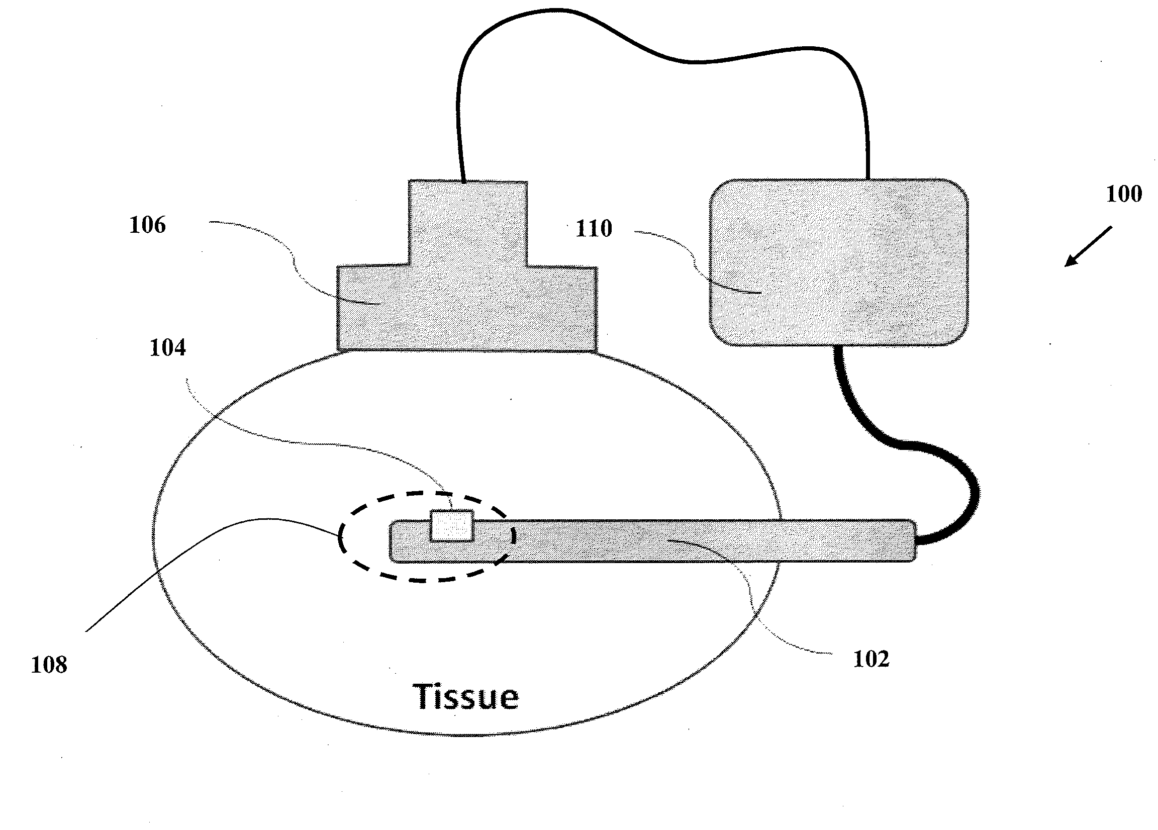
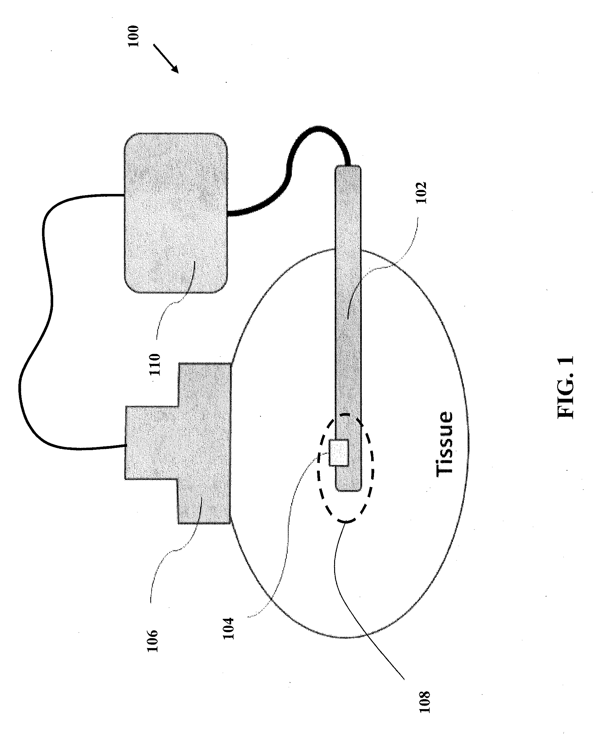
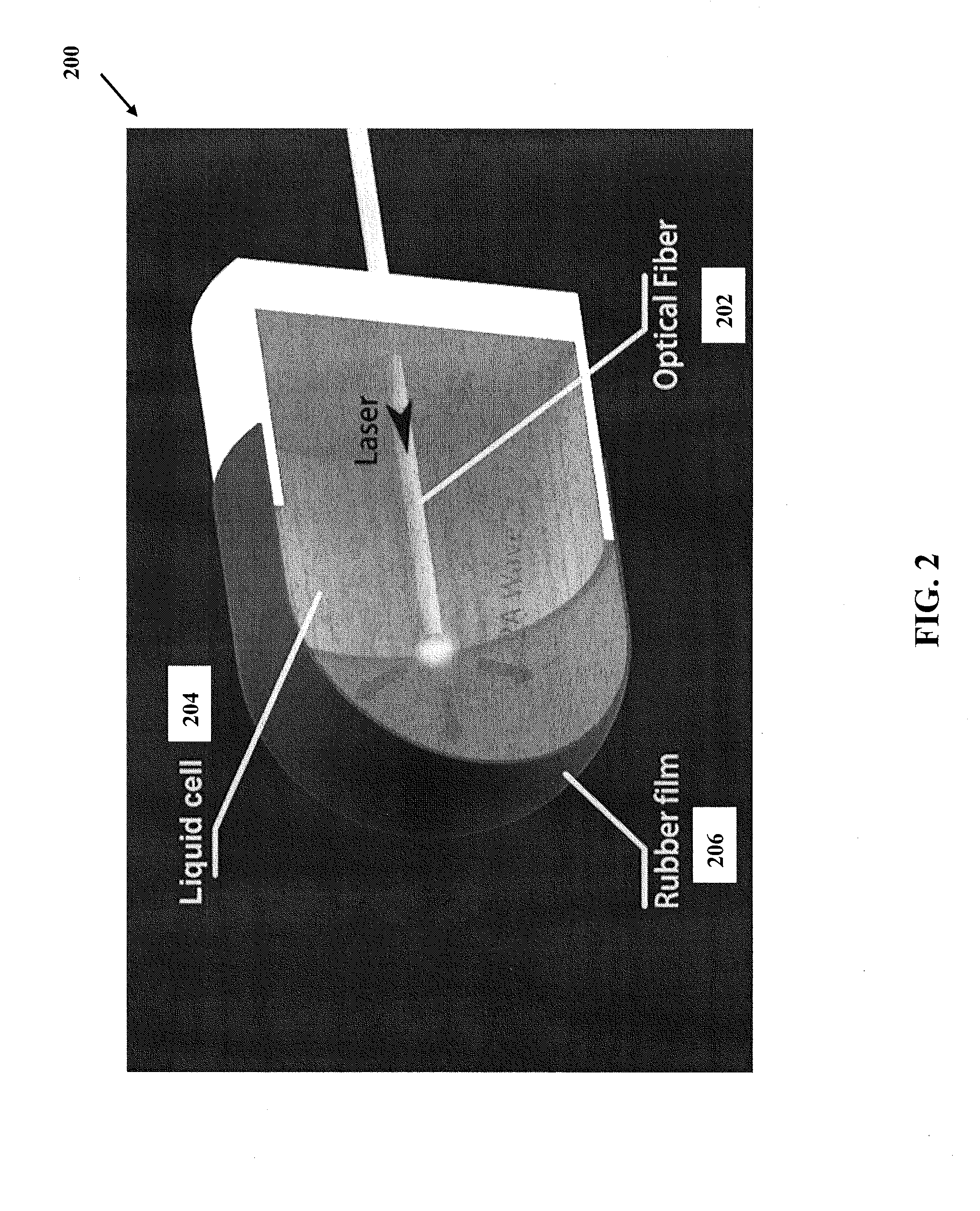
The invention is a system and method for monitoring in real-time the heating of tissue during an ablation procedure using interventional tools and ultrasound imaging. The system includes an ultrasound transmitter with a liquid cell and optical fiber, which sends out ultrasound signals to the tissue and receives them after they have been reflected or transmitted through the tissue. The received signals are processed to calculate the heating of the tissue in real-time. The technical effect of this system is to improve the precision and safety of the ablation procedure by providing in real-time information about the thermal dose delivered to the tissue.

Problems solved by technology

However, due to the low contrast between ablated and untreated tissue in the B mode image, conventional ultrasound imaging is usually not effective for the monitoring.
Other imaging modalities including CT and MRI can be incorporated with the ablation therapy and provide effective image guidance and monitoring; however, the requirements of these high-end imaging devices makes this approach unaffordable or inaccessible for many patients.
The radiation dose and magnetic field compatibility requirements also prevent these methods from being widely used.

Method used


Image

  • Real time ultrasound thermal dose monitoring system for tumor ablation therapy
  • Real time ultrasound thermal dose monitoring system for tumor ablation therapy
  • Real time ultrasound thermal dose monitoring system for tumor ablation therapy

Examples


Embodiment Construction

[0013]Some embodiments of the current invention are discussed in detail below. In describing embodiments, specific terminology is employed for the sake of clarity. However, the invention is not intended to be limited to the specific terminology so selected. A person skilled in the relevant art will recognize that other equivalent components can be employed and other methods developed without departing from the broad concepts of the current invention. All references cited anywhere in this specification, including the Background and Detailed Description sections, are incorporated by reference as if each had been individually incorporated.

[0014]The terms “light” and “optical” are intended to have a broad meaning. They can include, but are not limited to, the visible regions of the electromagnetic spectrum. They can also include nonvisible regions of the electromagnetic spectrum such as infrared and ultraviolet light, as well as visible regions.

[0015]The term “photoacoustic” is intended...


PUM


Abstract

An interventional system with real-time ablation thermal dose monitoring includes an interventional tool, an ultrasound transmitter at least one of attached to or integral with the interventional tool, an ultrasound receiver configured to receive ultrasound signals from the ultrasound transmitter after at least one of transmission through or reflection from a region of tissue while under an ablation procedure and to provide detection signals, and a signal processing system configured to communicate with the ultrasound receiver to receive the detection signals and to calculate, based on the detections signals, a thermal dose delivered to the region of tissue in real time during the ablation procedure.

Description

BACKGROUND[0001]1. Field of Invention[0002]The field of the currently claimed embodiments of this invention relates to thermal dose monitoring systems for tumor ablation therapy, and more particularly to real-time ultrasound thermal dose monitoring systems for tumor ablation therapy.[0003]2. Discussion of Related Art[0004]Tumor ablation therapy is one approach to remove tumor tissue by minimally invasive surgical procedures. In such procedures, an interventional tool is typically directed to a location within the patient's body that is either close to, or within tumor tissue. Energy is then delivered to the tumor tissue with a density and sufficiently rapidly to destroy tumor tissue by ablation. The interventional ablation tool can be a radio frequency ablation tool, or a laser ablation tool, for example. In the tumor ablation treatment, the safety and accuracy could be greatly improved if the operator is able to monitor the thermal dose in real time.[0005]In the tumor ablation oper...

Claims


Application Information

Patent Timeline
IPC IPC(8): A61B8/08A61N7/00A61B5/00
CPCA61B8/5223A61B5/0095A61N2007/0004A61N2007/0052A61N7/00A61B8/0841A61B8/085A61B18/1492A61B2018/00577A61B2018/263A61B2505/05A61N7/022G16H50/30
Inventor GUO, XIAOYUBOCTOR, EMAD M.JIANG, DENGRONG
Owner THE JOHN HOPKINS UNIV SCHOOL OF MEDICINE
Learn More