Bone Fixation System And Methods

a bone fixation system and bone technology, applied in the field of bone fixation system and methods, can solve the problems of gum health, grave periodontal disease, discomfort and ailments, etc., and achieve the effects of reducing periodontal disease, preventing possible nerve or root damage, and improving the stability of the im

Active Publication Date: 2015-12-10
MONTEJO JAVIER
View PDF10 Cites 5 Cited by
  • Summary
  • Abstract
  • Description
  • Claims
  • Application Information

AI Technical Summary

Benefits of technology

[0012]The system of the present invention is innovative because it does not use teeth as an anchorage point, thereby reducing periodontal disease and improving the stability of the IMF. The system distances itself from possible alveolus bone engagement, thereby preventing possible nerve or root damage.
[0013]The invention comprises a bone fixation and / or orthodontic realignment system that utilizes a bone anchorage screw with internal threading for receiving an orthodontic screw or rail bar orthodontic screw. In additional embodiments, a bone anchorage screw is used with an additional externally threaded screw extending from its head that can be set using either a nut or capped nut. The invention further comprises a T-shaped orthodontic bar, a flexible rail bar with rounded edges, or C-shaped flexible rail bar with an internal space for accommodating nuts. The figures discussed below show, collectively, an adaptable and easily customizable system for particular uses, such as for fracture reduction, intermaxillary fixation, or for dental realignment.

Problems solved by technology

Notwithstanding their functionality, these systems have a number of disadvantages for both patient and surgeon, being the health of the gums the main issue at hand after their prolonged use.
For the patient, these systems cause discomfort and ailments in cases when the injuries are reversible, and when irreversible, they can produce grave periodontal disease.
For the surgeon, these fixation systems require the existence of intact teeth in order to perform the procedure, a situation that is often difficult when faced with severe fractures.
Additionally, their troublesome wire-based installation represents a biological hazard.
This system, however, has disadvantages.
For example, it does not provide sufficient stability to the fixation, producing posterior open bites.
Additionally, bone fragments can be twisted upon tightening the wires, they cannot provide a tension band effect, and they cannot be used for fractures between teeth or when post treatment requires the use of elastic IMF.
Furthermore, their installation is difficult in complex traumas.
This device does provide for modular placement of the IMF bone screws, but carries the same disadvantages of the arch bar and bone screws of the prior art systems.
The system has a plurality of hooks that sustain a wire or elastic, an arch bar that is laid upon the gums (making cleanliness difficult), and the placement of IMF self-tapping bone screws between the roots of teeth (potentially causing root and nerve damage).
Notwithstanding their functionality, these systems have a number of disadvantages for both patient and surgeon.
In the case of the traditional screw mechanism, their placement is the most inconvenient due to the location of the tooth apex.
Regarding the mini plates systems, their biggest surgical difficulty lies in the difficulty of their insertion.
For the patient, these systems can damage the dental roots due to their proximity to the screws.
For the surgeon, the biggest inconvenience is the high level of difficulty of locating the screws in possible and limited spaces without altering the anatomy and physiology of the bone and the tooth.

Method used


Image

  • Bone Fixation System And Methods
  • Bone Fixation System And Methods
  • Bone Fixation System And Methods

Examples


Embodiment Construction

[0025]The following describes one manner in which the invention is to be performed. However, it should be understood that these described embodiments do not limit the inventive concept of the technology, and it is written for the best comprehension of the technology's essential components.

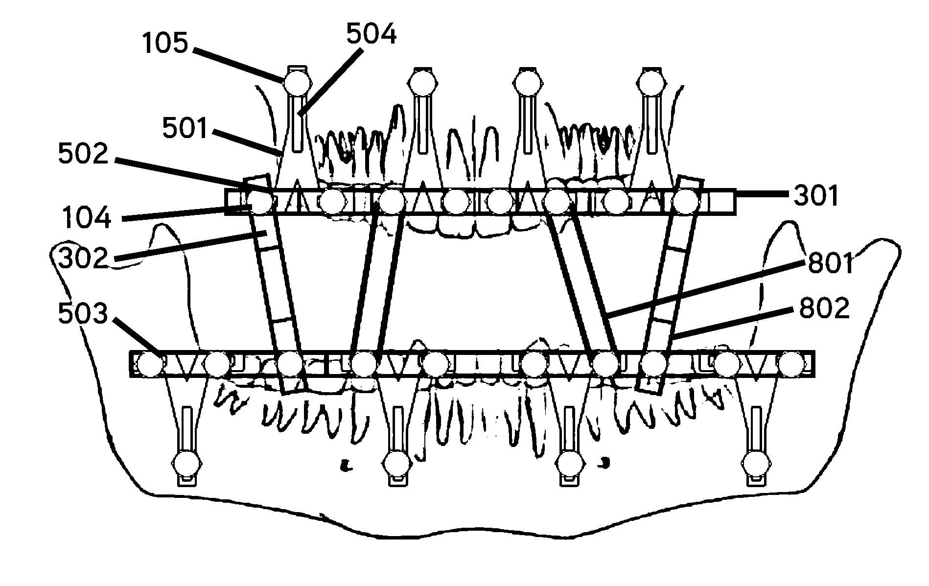
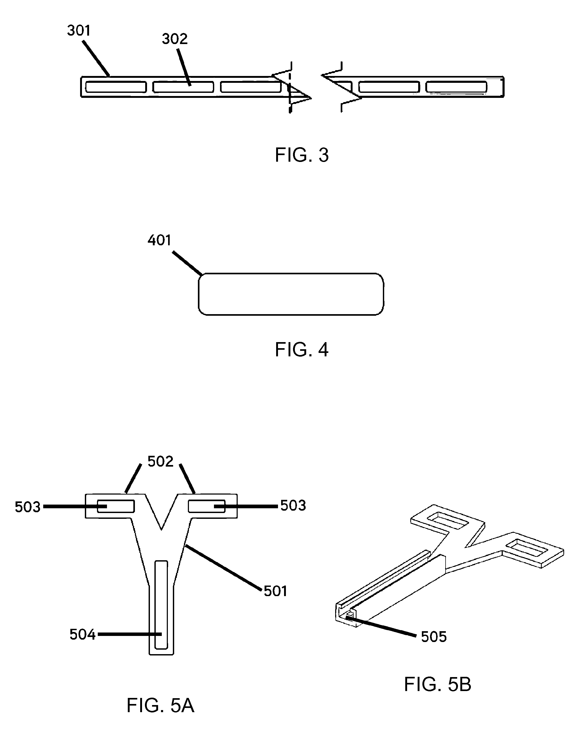
[0026]An object of the present invention is to provide a bone anchorage system comprising a smooth flexible rail laminate (301) with rounded edges anchored to the maxillary bone, secured through the use of a tiered bone screw (101) and T-shaped bar (501) that, once installed, works for IMF through the use of additional linking materials (801) such as bars, wires, elastics or plastic straps. The present invention also allows for positioning orthodontic anchorage systems at any point on the bar through the use of screws placed on the rail bar or an extension system on the occlusal plane, as is proposed with the T-shaped bar (501).

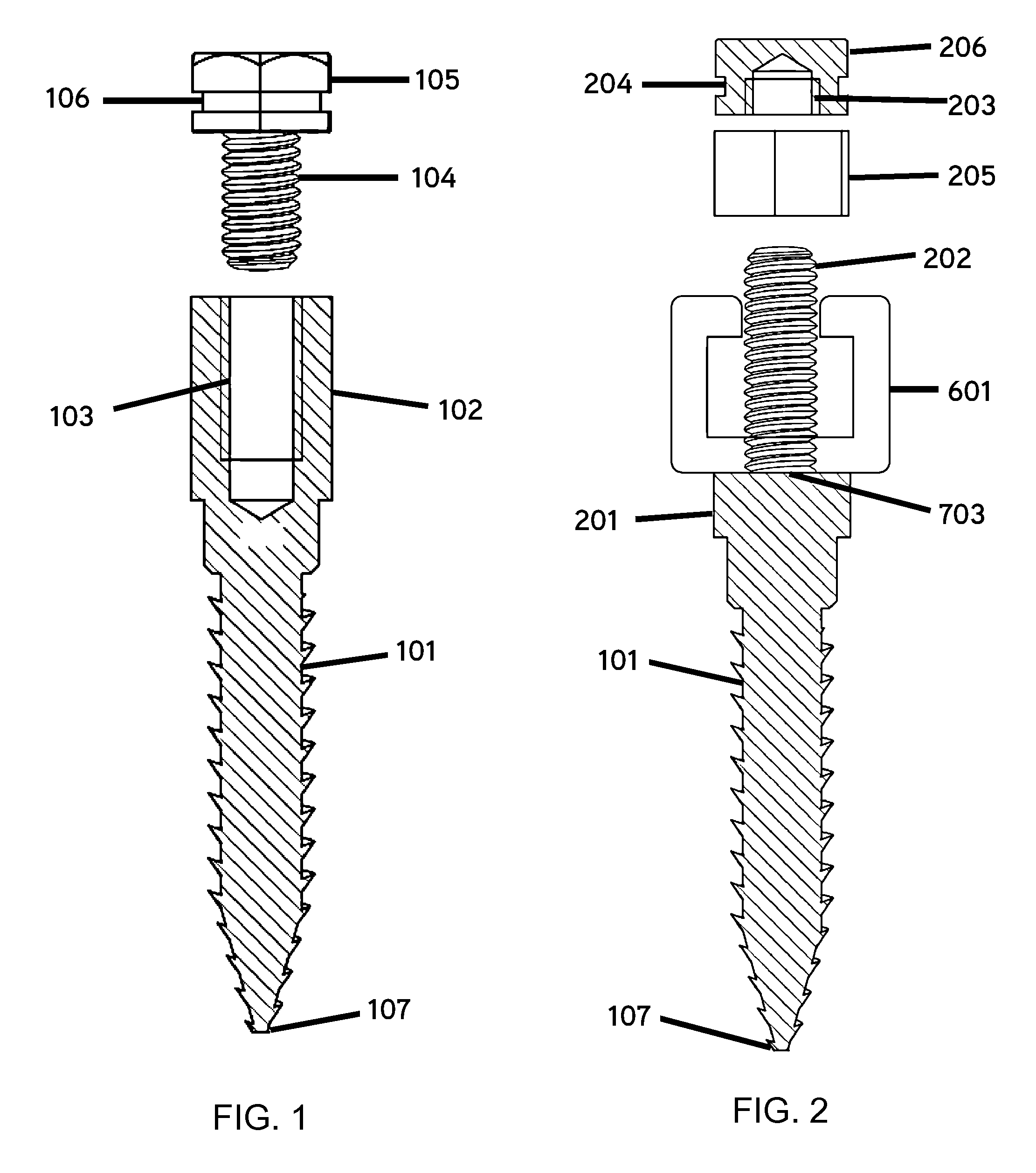
[0027]In one exemplary embodiment, one or more bone anchorage screws (1...


PUM


Abstract

An intermaxillary fixation system is provided, including a bone anchorage screw having at least one of an elongated head with internal threading and an externally threaded screw extending from a head of the bone anchorage screw, a fixation system, and a rail bar. A method for the stabilization and fixation of maxillary and mandibular arches is also provided, including setting a plurality of bone anchorage screws to the maxillary and mandibular arch, each bone anchorage screw having a head, fixing one or more T-shaped bars to the bone anchorage screws, bending and connecting a rail bar to heads of the one or more T-shaped bars with orthodontic screws, and wrapping a connector between the heads of the bone anchorage screws located on the mandibular arch and the maxillary arch.

Description

FIELD OF THE INVENTION[0001]The present invention relates, in general, to the fixation of bone fractures, and more particularly to maxillary or mandibular stabilization or reduction of any possible fractured bone fragments.[0002]The present invention also relates to the fixation of bone fractures in orthodontic circumstances where there is a need for bone space in order to perform dental movements.BACKGROUND OF THE INVENTION[0003]Within the field of oral and maxillofacial surgery one of the most important phases in the handling of fractures is intermaxillary fixation (IMF), due to the fact that during this step, the patient's original occlusion is reestablished.[0004]Historically, intermaxillary fixation systems have been based on the use of teeth as anchorage for interdental surgical wires such as Erich, Ivy or Kazanjian arch bars, which are used in procedures that require maxillary fracture reductions. Notwithstanding their functionality, these systems have a number of disadvantag...

Claims


Application Information

Patent Timeline
Patent Type & Authority Applications(United States)
IPC IPC(8): A61B17/68A61C8/00A61C7/36A61B17/86
CPCA61B17/683A61C7/36A61C8/0096A61B17/8605A61B17/6433A61B17/663A61B17/864
Inventor MONTEJO, JAVIER
Owner MONTEJO JAVIER
Why Eureka
Try Eureka