System for sensing particulate matter

Inactive Publication Date: 2015-12-10
FORD GLOBAL TECH LLC
View PDF2 Cites 28 Cited by
  • Summary
  • Abstract
  • Description
  • Claims
  • Application Information

AI Technical Summary

Benefits of technology

[0006]In this way, a PM sensor may be exposed to a more uniform flow distribution across its surface. By guiding the sample of exhaust gases through two sets of apertures, the flow rate of the sample of exhaust gases may be controlled. Further, the flow rate may be more even as it impinges on the surface of the PM sensor allowing for a more uniform deposition of particulates. By providing a more even and controlled flow rate of the sample of exhaust gases onto the PM sensor surface, sens

Problems solved by technology

Particulate matter sensors may encounter problems with non-uniform deposition of soot on the sensor due to a bias in flow distribution across the surface of the sensor.
Further, particulate matter sensors may be prone to contamination from an impingement of wate

Method used


Image

  • System for sensing particulate matter
  • System for sensing particulate matter
  • System for sensing particulate matter

Examples


third embodiment

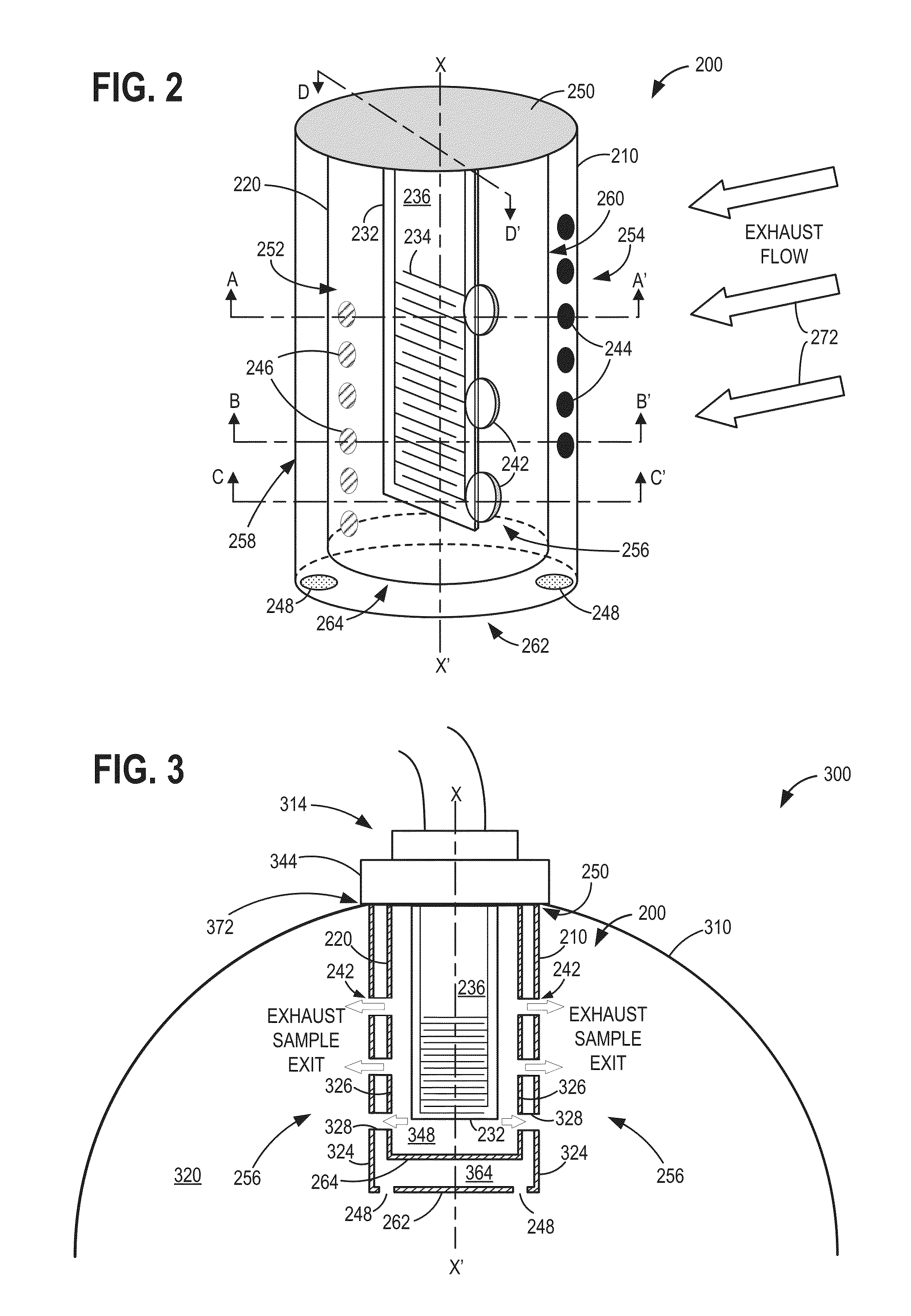
[0022]A portion of exhaust gases may be drawn into the first outer tube of the PM sensor assembly whereupon the portion of gases may flow within an annular space between the first outer tube and the second inner tube and eventually enter the second inner tube (FIGS. 4a, 4b, and FIG. 7). The portion of exhaust gases may then impinge on a surface of the PM sensor bearing an electrical circuit. Finally, the portion of exhaust gases may exit the inner tube via channels on side surfaces of the PM sensor assembly as shown in FIGS. 4a and 4c. Exhaust flow in the exhaust passage past the PM sensor assembly may create low static pressure zones at the side surfaces of the PM sensor assembly (FIGS. 5 and 6). The PM sensor assembly may be placed in a reversed orientation such that a sample of exhaust gas enters the first outer tube from apertures on a downstream surface, flows through an annular space between the first outer tube and the second inner tube, and enters the second inner tube from ...

embodiment 800

[0079]Turning now to FIG. 8, it portrays an alternative embodiment 800 of the PM sensor assembly 200 of FIGS. 2-4. PM sensor assembly 800 is formed in a similar manner to PM sensor assembly 200 but is arranged in an exhaust passage in an opposite orientation. Specifically, PM sensor assembly 800 is arranged such that the intake apertures on the first outer tube are on a downstream surface of the first outer tube. Additionally, intake apertures on the second inner tube are positioned on an upstream surface of second inner tube. In other words, PM sensor assembly 800 is positioned in reverse orientation to PM sensor assembly 200 with respect to direction of exhaust flow from the DPF.

[0080]In the embodiment shown in FIG. 8, exhaust gases flow from the left hand side to the right hand side of FIG. 8. Thus, PM sensor assembly 800 is portrayed from an upstream perspective. An arrangement such as the one in FIG. 8 may be used in engines with larger displacements wherein an exhaust mass flo...

embodiment 1100

[0093]Turning now to FIG. 11, it portrays yet another embodiment 1100 of a PM sensor assembly. Specifically, embodiment 1100 features a single protective tube surrounding the PM sensor unlike PM sensor assemblies 200 and 800 which feature two protective tubes around their respective PM sensors.

[0094]In the embodiment shown in FIG. 11, exhaust gases flow from the right hand side to the left hand side of FIG. 11. Thus, PM sensor assembly 1100 is viewed from a downstream perspective.

[0095]PM sensor assembly 1100 includes a protective tube 1120 with a plurality of intake apertures 1146 on a downstream surface 1152 of protective tube 1120. An upstream surface 1154 of protective tube 1120 is substantially normal to and faces oncoming exhaust gas flow. Protective tube 1120 also includes multiple exit apertures 1148 on its side surfaces 1156. Further, a PM sensor 1132 may be positioned within protective tube 1120. A first surface 1136 of PM sensor 1132 may feature an electrical circuit 1134...


PUM


Abstract

Systems and methods are described for sensing particulate matter in an exhaust system of a vehicle. An example system comprises a first outer tube with a plurality of intake apertures on an upstream surface, a second inner tube with a plurality of intake apertures on a downstream surface, and a particulate matter sensor placed within the second inner tube. The second inner tube may be positioned within the first outer tube such that a central axis of the second inner tube is parallel to a central axis of the first outer tube.

Description

TECHNICAL FIELD[0001]The present application relates to sensing particulate matter in an exhaust system.BACKGROUND AND SUMMARY [0002]Engine emission control systems may utilize various exhaust sensors. One example sensor may be a particulate matter sensor which indicates particulate matter mass and / or concentration in the exhaust gas. In one example, the particulate matter sensor may operate by accumulating particulate matter over time and providing an indication of the degree of accumulation as a measure of exhaust particulate matter levels.[0003]Particulate matter sensors may encounter problems with non-uniform deposition of soot on the sensor due to a bias in flow distribution across the surface of the sensor. Further, particulate matter sensors may be prone to contamination from an impingement of water droplets and / or larger particulates present in the exhaust gases. This contamination may lead to errors in sensor output. Furthermore, sensor regeneration may be inadequate when a...

Claims


Application Information

Patent Timeline
IPC IPC(8): G01N15/06G01M15/10
CPCG01M15/102G01N15/0656F01N13/008F01N2560/05G01N15/0606G01N33/0011
Inventor ZHANG, XIAOGANG
Owner FORD GLOBAL TECH LLC
Why Eureka
Try Eureka