Backlight and Display Device

a backlight and display device technology, applied in the field of display technology, can solve the problems of moiré effect, black lines, adverse impact on the normal display etc., to avoid defects, avoid damage to the lower polarizer of the liquid crystal display panel, and small width

Active Publication Date: 2015-12-10
BOE TECH GRP CO LTD +1
View PDF9 Cites 8 Cited by
  • Summary
  • Abstract
  • Description
  • Claims
  • Application Information

AI Technical Summary

Benefits of technology

[0014]In the backlight provided by the present invention, an optical film set is fixed on a supporting part of a frame by using a fixing member, but is not pressed onto a light guide plate by using a supporting part. Accordingly, the supporting part may have a relative small width, that is, the end of the supporting part is located outside the effective display area of the liquid crystal display panel. Therefore, a black frame can be prevented from appearing in the effective display area when the display device including the backlight displays.
[0015]The fixing member covers ear parts of a plurality of optical films, such that the optical film set is pressed onto the frame. Therefore, the optical films can be prevented from being wrapped. Accordingly, it is possible to avoid defects such as black lines and moiré effect when the display device including the backlight displays. Furthermore, it is possible to avoid the damage to the lower polarizer of the liquid crystal display panel.

Problems solved by technology

The supporting part of the frame 120 extends into the effective display area, resulting in a black frame formed within the effective display area and thus causing an adverse impact on the normal display of the liquid crystal display panel.
Accordingly, although the implementation shown in FIG. 2 can prevent a black frame from appearing in the effective display area, to a certain extent, the optical film is easily to be wrapped due to not being pressed, which leads to black lines, moiré effect, damage to the lower polarizer of the liquid crystal display panel, and the like.

Method used


Image

  • Backlight and Display Device
  • Backlight and Display Device
  • Backlight and Display Device

Examples


Embodiment Construction

[0026]Specific embodiments of the present invention will be described as below in details with reference to the accompanying drawings. It should be understood that the specific embodiments described herein are merely used for describing and explaining the present invention, but are not intended to limit the present invention.

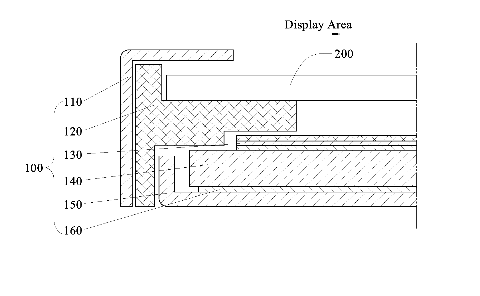
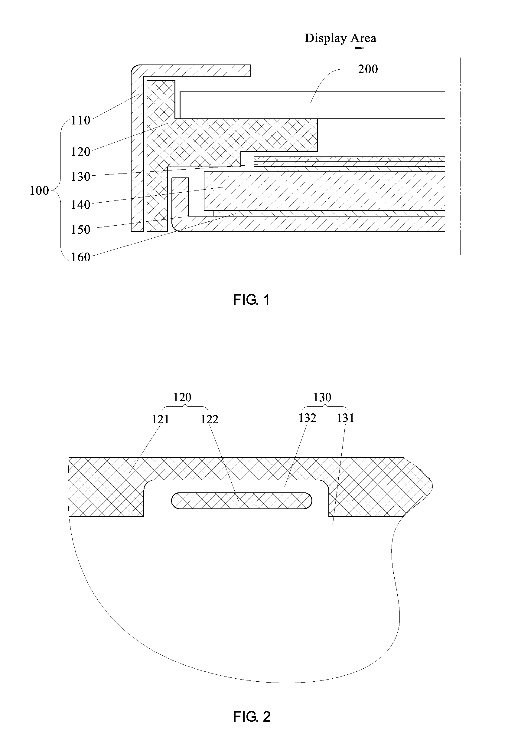
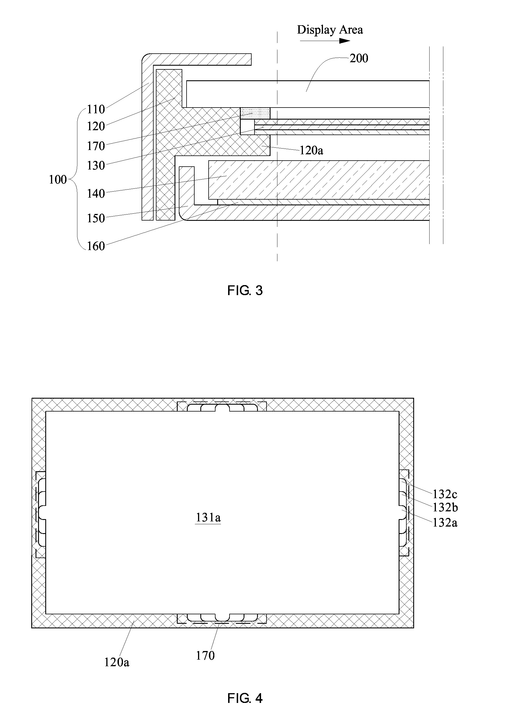
[0027]As an aspect of the present invention, as shown in FIG. 3, a backlight is provided. The backlight includes a frame 120 and an optical film set 130, and the optical film set 130 includes a plurality of optical films that are successively stacked, wherein the backlight further includes a fixing member 170, the frame 120 includes a supporting part 120a protruding toward the middle part of the backlight, and the optical film set is provided on the supporting part 120a. As shown in FIG. 4 and FIG. 5, each optical film in the optical film set 130 includes a film body and ear parts protruding from the sides of the film body. In any two adjacent optical films, the...


PUM

PropertyMeasurementUnit
areaaaaaaaaaaa
widthaaaaaaaaaa
opticalaaaaaaaaaa

Abstract

The present invention provides a backlight and a display device. The backlight includes a frame and an optical film set including a plurality of optical films that are successively stacked. Each optical film in the optical film set includes a film body and an ear part. In any two adjacent optical films, the boundary of at least one side of the ear part of the lower optical film extends beyond the boundary of the same side of the ear part of the upper optical film. A fixing member covers the ear parts of the plurality of optical films, such that the optical film set is fixed on the frame, and the fixing member can fix the relative positions among the plurality of optical films in the optical film set. In the backlight, the optical film set is reliably fixed without affecting the normal display on the display device.

Description

FIELD OF THE INVENTION[0001]The present invention relates to the field of display technology, and particularly, to a backlight and a display device including the backlight.BACKGROUND OF THE INVENTION[0002]As shown in FIG. 1 (the prior art), a liquid crystal display device generally includes a liquid crystal display panel 200 and a backlight 100 providing a light source for the liquid crystal display panel 200, wherein the backlight 100 includes a metal frame 110, a frame 120, an optical film set 130, a light guide plate 140, a rear plate 150, a reflector plate 160 and light emitting elements (not shown). As shown in FIG. 1, the frame 120 is provided between the side wall of the metal frame 110 and the side wall of the rear plate 150. The frame 120 has a supporting part formed protruding toward the middle part of the backlight. This supporting part can fix the optical film set 130, the light guide plate 140 and the reflector plate 160 onto the rear plate 150, while the upper surface ...

Claims


Application Information

Patent Timeline
Patent Type & Authority Applications(United States)
IPC IPC(8): G02F1/1335F21V8/00
CPCG02F1/1336G02B6/005G02B6/0031G02F1/133608G02F2201/54G02B6/0088G02F1/133322G02F1/133317
Inventor GUO, JUNJIEZHAO, HONGYUHAO, YUTAOLV, JINKU
Owner BOE TECH GRP CO LTD
Why Eureka
Try Eureka