Light Bulb Installation and Removal Tool

a technology for installing and removing tools and light bulbs, which is applied in the manufacture of wrenches, screwdrivers, electrode systems, etc., can solve the problems of protruding flame tips, light bulbs that are difficult to remove and replace, so as to facilitate angled gripping applications, easy to interchange components, and increase the accessibility of exposed areas

Inactive Publication Date: 2015-12-10
SNATCHER
View PDF12 Cites 7 Cited by
  • Summary
  • Abstract
  • Description
  • Claims
  • Application Information

AI Technical Summary

Benefits of technology

[0017]An installation and removal tool for light bulbs and similar items is designed to increase accessibility of exposed or recessed light bulbs in elevated locations. The device comprises modular and interchangeable components: one or more attachment heads, a pole, an articulating joint, and an extraction head. Each embodiment of the attachment heads includes a gripping unit and a handle that is configured to cooperate with a telescoping pole and to cooperate with a user's hand when a telescoping pole is not needed. Each gripping unit has a geometry designed to cooperate with one or more light bulb shapes and / or sizes and further comprises an adhesive system. Three embodiments of the gripping unit are specifically designed with a multi-diameter cup and a bulb cavity comprising a release lip and engagement surface for cooperating with various sizes of popular light bulb designs including flame tip designs. Another embodiment of the gripping unit is specifically designed with two extensions for cooperating with linear tube or spiral design bulbs. The adhesive system comprises a mounting component that attaches the adhesive system to the gripping unit, an adhesive component that comprises a pressure sensitive adhesive and attaches to the mounting component with hook and loop fasteners, and a protective liner that cooperates with the adhesive component to preserve the functionality of the adhesive when it is not in use. Optionally, the adhesive system can also include a spacer combined with a second adhesive system. The adhesive components are configured such that an air channel surrounds the adhesive components and is defined by the bulb cavity release lip, bulb cavity engagement surface, and outer edge of the adhesive system. The adhesive components are further configured such that a light bulb with an oddly shaped distal end can protrude through an opening defined by the adhesive components. The articulating joint comprises an articulating flexible knuckle arrangement configured to facilitate angled gripping applications. The extraction head comprises a broken bulb extraction assembly configured to cooperate with a light bulb base cap. The modular and interchangeable components can be used together or individually depending on the location and type of bulb or application. The components are preferably combined in a kit to allow the user to easily interchange components as needed.

Problems solved by technology

Light bulbs can be difficult to remove and replace, for example, where they are located beyond someone's reach, where they are offset from a traditional substantially vertical orientation, or where they are tightly fit in a light fixture due to age or over-tightening.
Additionally, light bulbs can be difficult to remove and replace due to their size, shape, or construction and materials.
The most difficult styles are those with the protruding flame tip, which is extremely fragile and readily broken.
The others are difficult due to their thin lined and semi-pointed designs.
Compact fluorescent bulbs, often referred to as compact fluorescent lamps (CFLs), are also difficult to remove and replace because they are easily broken, especially the linear designed CFLs.
Both spiral and linear CFLs are constructed with one or more small U-shaped (biaxial) straight or twisted glass tubes that are more fragile than incandescent bulbs due to manufacturing defects such as deformations in their walls and due to the lack of additional support especially for bulbs with a long length relative to its diameter.
Applying centripetal / torsion forces during an installation or removal either with one's hands or with an ordinary light bulb removal tool may cause the ends of the tubes to flex towards each other causing one or more of the tubes to shatter.
Shattered CFLs pose a risk of laceration from the glass itself and of exposing one to toxic reactions to phosphor, which is used to coat the inside of the CFL tubes.
Each tool or design, however, has drawbacks.
Unfortunately, the suction cup design is limited to a small segment of commercially available light bulb designs.
The suction cup design will not work with light bulbs that have insufficient surface shape and area for creating adequate suction, and / or a contaminated surface.
Unfortunately, the finger gripping designs do not work with all shapes of light bulbs or close fitting decorative fixture surrounds, and generally are difficult to properly orient and use.
Unfortunately, like the other designs, the recessed cup design does not work with all shapes of light bulbs, exhibits early age deterioration with increased brittleness and stiffness, and are generally is difficult to use.
Despite efforts to pad the gripping components of the jaw gripping design, it is still possible to break the light bulb when using the tool.
Additionally, it does not work with a wide variety of bulb shapes.
Unfortunately, like the other designs, the split compression tool may break the bulb and does not work with a wide variety of bulb shapes.
Unfortunately, the known adhesive designs incorporate adhesives that harden after one or two uses rendering the tool a single-use tool such as the tool described in U.S. Pat. No. 558,573 issued to Hunt et al.
Unfortunately, layering multiple adhesive sheets introduces a further problem as the sheets will twist and separate when the tool is used to remove a bulb.
For each of the types of installation and removal tools available, none are configured to assist with removing bulbs in light figures that are mounted at odd angles.
For each of the types of installation and removal tools available, none also provide an extraction component for cooperating with broken bulbs.
Unfortunately, the known designs tend to deform the shape of the base and make it more difficult to remove from the socket.

Method used


Image

  • Light Bulb Installation and Removal Tool
  • Light Bulb Installation and Removal Tool
  • Light Bulb Installation and Removal Tool

Examples


first embodiment

of Gripping Unit

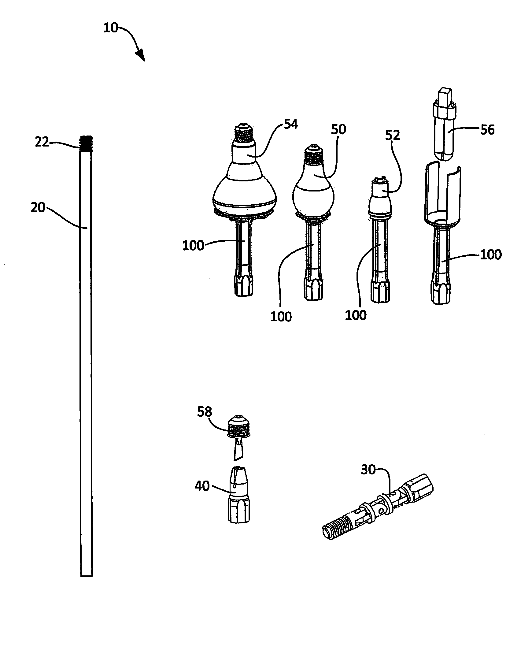
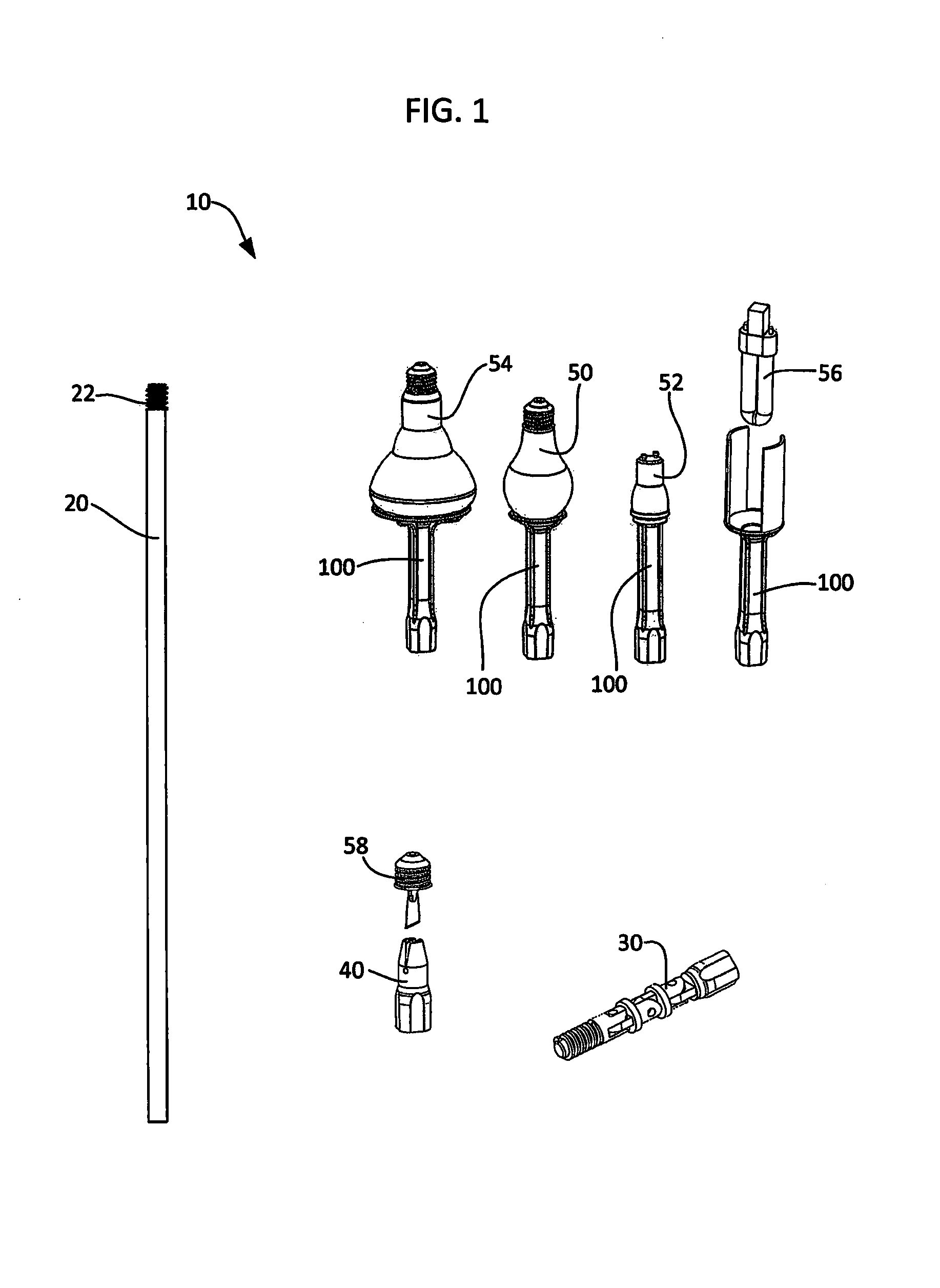
[0062]FIGS. 6-10 illustrate the first embodiment of the gripping unit 110, which cooperates with at least traditional incandescent bulbs 50. Gripping unit 110 attaches to or is integral with handle 104 at its distal end 104a. Gripping unit comprises a platform or bulb cavity 112 having an engagement surface 112a on which the adhesive system 120 attaches. Bulb cavity 112 and engagement surface 112a further define an opening 112b that cooperates with and is in fluid communication with the bore 106 defined by handle 104. Preferably, the bulb cavity 112 is generally concave in shape with a substantially flat release lip 114 around its circumference as shown in the Figures. Adhesive system 120 covers less than all of the engagement surface 112a such that an air channel 116 is defined by the outer edge 120a of adhesive system 120, the exposed surface area of the engagement surface 112a, and the release lip 114 of the bulb cavity.

[0063]The air channel 116 is configured such...

second embodiment

of Gripping Unit

[0068]FIGS. 11-14 illustrate the second embodiment of the gripping unit, which cooperates with smaller bulbs such as mini spotlight bulbs 52. Generally, the second embodiment of the gripping unit is configured like the first gripping unit but with slightly smaller dimensions to accommodate smaller light bulbs and a flat or substantially flat bulb cavity engagement surface 112a. In particular, the diameter of the overall bulb cavity engagement surface 112a plus release lip 114 is preferably about 1.125 inches. Additionally, the adhesive system 120 is preferably circular in shape and optionally further defines a circular opening at the center of each of its components. Further, it is preferable that the opening 122b defined by the mounting component 122 is sized slightly larger in diameter than the opening 124b defined by the adhesive component. Preferably, the openings 122b and 124b range in size between 0.25 inches and 0.3125 inches for the second embodiment of the g...

third embodiment

of Gripping Unit

[0070]FIGS. 15-18 illustrate the third embodiment of the gripping unit, which cooperates with larger light bulbs such as those used with flood lights 54. Generally, the third embodiment of the gripping unit is configured like the first and second gripping units but with larger dimensions to accommodate larger light bulbs. In particular, the diameter of the overall bulb cavity engagement surface plus release lip is preferably about 3.50 inches. Additionally, the adhesive system 120 is preferably circular in shape and further defines a preferably circular opening at the center of each of its components. Further, it is preferable that the opening 122b defined by the mounting component 122 is sized slightly larger in diameter than the opening 124b defined by the adhesive component. Preferably, the openings 122b and 124b range in size between 0.25 inches and 0.875 inches for the second embodiment of the gripping unit.

[0071]The radius required to maintain an appropriate co...


PUM


Abstract

An installation and removal tool for light bulbs and similar items comprising modular and interchangeable attachment heads, a pole, an articulating joint, and an extraction head. Attachment heads comprise a gripping unit and a handle and are each configured to cooperate with one or more light bulb shapes and / or sizes and further comprises an adhesive system. Several embodiments of the gripping unit comprise a bulb cavity with an engagement surface and a release lip and an adhesive system mounted on the engagement surface such that an air channel is created surrounding the adhesive system. The adhesive system comprises pressure sensitive adhesive and preferably defines an opening in fluid communication with a bore defined by the handle to accommodate extended and oddly shaped bulbs. A protective liner that cooperates with the adhesive component to preserve the functionality of the adhesive when it is not in use.

Description

CROSS-REFERENCE TO RELATED APPLICATIONS[0001]This application claims the benefit of co-pending U.S. application Ser. No. 14 / 507,029 filed Oct. 6, 2014, which claims the benefit of provisional U.S. Application No. 62 / 007,691 filed Jun. 4, 2014.FIELD OF INVENTION[0002]This invention relates to light bulbs and tools for installing and removing light bulbs. More particularly, this invention relates to an installation and removal tool for multiple types, shapes, and installations of light bulbs and for removal and installation of light bulbs positioned in remote or inconvenient locations.BACKGROUND OF THE INVENTION[0003]Each year there are several millions of light bulbs sold around the globe. The typical residence with today's modern architecture utilizes approximately fifty light bulb fixtures, with an additional increased amount for exterior lighting and landscape illumination. These light bulbs are available in an exceptionally wide variety of designs with various shapes, dimensions ...

Claims


Application Information

Patent Timeline
Patent Type & Authority Applications(United States)
IPC IPC(8): H01J9/00B25B23/00H01K3/32B25B9/02
CPCH01J9/006H01K3/32B25B23/0035B25B9/02B25B11/007H01J9/003
Inventor SHAPS, ROBERTNEAL, MURRAY
Owner SNATCHER
Why Eureka
Try Eureka