

Terminal, Wire Connecting Structure and Method of Manufacturing A Terminal
a technology of wire connecting structure and manufacturing method, which is applied in the manufacture of contact member materials, coupling contact members, and material of connection contact members, etc., can solve the problems of large increase in the manufacturing process of wire harnesses, inability to miniaturize or have a higher density of wire harnesses, and inability to meet the needs of the customer, so as to reduce the width and reduce the width
Active Publication Date: 2015-12-10
FURUKAWA ELECTRIC CO LTD +1
View PDF3 Cites 21 Cited by
- Summary
- Abstract
- Description
- Claims
- Application Information
AI Technical Summary
Benefits of technology
The patent describes a method for making a terminal with a connector portion and a tubular crimp portion for crimping onto an electric wire. The method involves shaping a metal base material with specific area ratios and forming a metal layer on top of the base material to form a metal member. The metal member is then pressed to form a tubular body with the same area ratio as the crimp portion. A welding process is used to create a patent text describes a method for making a terminal with a connector and crimp portion. The crimp portion is designed to enclose the end of an electric wire. The method involves forming a metal base material with specific area ratios and adding a metal layer on top of it. The metal is then pressed to create a tubular body with the same area ratio as the crimp portion. The crimp portion is welded to securely hold the electric wire and prevent it from moving or becoming dislodged during use. This method ensures reliable adhesion between the crimp and the wire after aging.
Problems solved by technology
Accordingly, since there is a possibility that exposed aluminum produces dissimilar metal corrosion and the conductor becomes defective at a connecting portion between the conductor and the terminal that are made of the aforementioned materials, it is necessary to take measures such as to shield the aluminum conductor from the outside world.
However, this results in a bulky connector since the size of a connector housing needs to be larger because of a bulky mold portion, and thus a wire harness as a whole cannot be miniaturized or have a higher density.
With a molding method, since individual crimp portion is processed after the crimping of an electric wire, there is a problem that manufacturing processes of a wire harness may largely increase or become cumbersome.
However, when laser welding is performed, since the weld portion is forcibly dissolved rapidly and then rapidly solidified, a strain is produced in the weld portion.
This strain affects adhesion between the crimp portion and an electric wire, and particularly, it is difficult to maintain reliability after aging.
Method used
View moreImage
Smart ImageViewing Examples

Examples
example 1
[0062]Using a Cu-2.3% Ni-0.6% Si-0.15% Sn-0.5% Zn-0.1% Mg alloy, a plate was fabricated with process I described below.
example 2
[0063]Using a Cu-0.27% Cr-0.25% Sn-0.2% Zn alloy, a plate was fabricated with process I described below.
example 3
[0064]Using a Cu-0.15% Sn-trace amount P alloy, a plate was fabricated with process II described below.
[0065]Process I: Casting→heat treatment (600° C., 5 h)→heat to 850° C. and perform hot rolling (rolling reduction 83%)→cold rolling (rolling reduction 95%)→solution (825° C., 15 s)→aging treatment (460° C., 2 h)
[0066]Process II: Casting→heat to 800° C. and perform hot rolling (rolling reduction 83%)→cold rolling (rolling reduction 92%)→recrystallization process (400° C., 2 h)→finish rolling (reduction 40%)
Login to View More PUM
| Property | Measurement | Unit |
|---|---|---|
| thickness | aaaaa | aaaaa |
| thickness | aaaaa | aaaaa |
| diameter | aaaaa | aaaaa |
Abstract
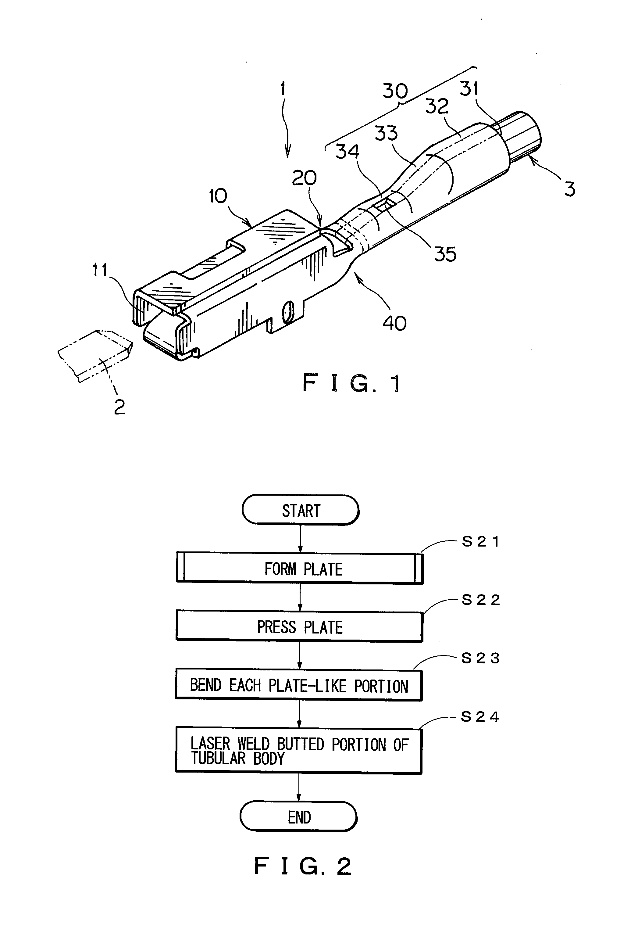
A terminal includes a connector portion electrically connectable to an external terminal, a tubular crimp portion formed integrally or separate from the connector portion and crimps with a wire, and a transition portion coupling the two. The tubular crimp portion of a copper or copper alloy metal base material or a metal member having the same is a tubular member closed on transition portion side and reduces in diameter towards the transition portion side such that a conductor-end portion of the electric wire is un-exposed. The tubular crimp portion has a belt-shaped weld portion along a longitudinal direction of the tubular crimp portion. A circumferential direction of the tubular crimp portion matches the RD-direction of the base material. A sum of area ratios R1, R2 and R3 in a rolling plane of the base material, of Cube-, RDW-, and Goss-oriented crystal grains, respectively, is greater than or equal to 15%.
Description
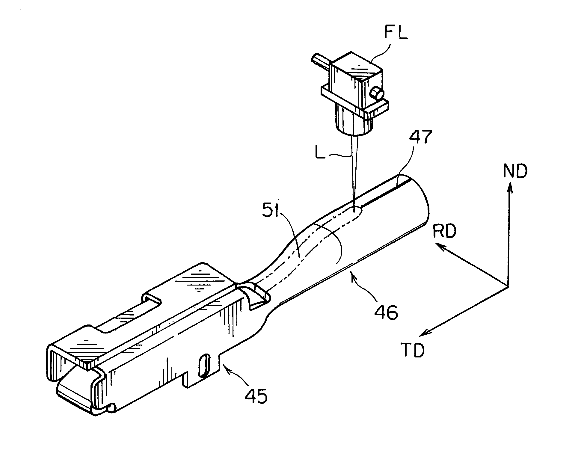
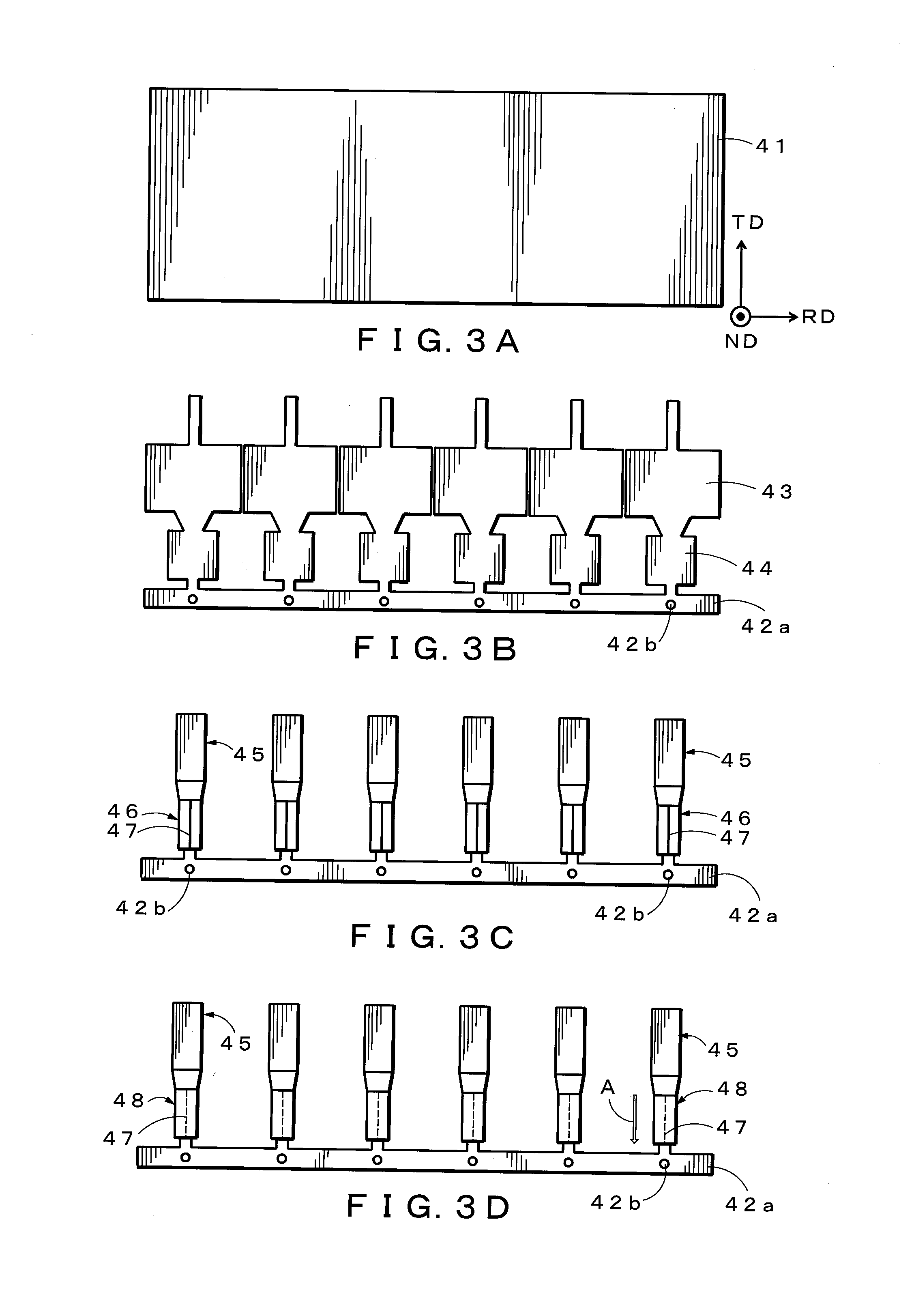
[0001]This is a continuation application of International Patent Application No. PCT / JP2014 / 050147, filed Jan. 8, 2014, which claims the benefit of Japanese Patent Application No. 2013-034024, filed Feb. 23, 2013. This application is entitled to participation in the patent prosecution highway program because of corresponding Japanese Patent Application No. 2014-506656, which claims the benefit of International Patent Application No. PCT / JP2014 / 050147, filed Jan. 8, 2014, which claims the benefit of Japanese Patent Application No. 2013-034024, filed Feb. 23, 2013, the full contents of all of which are hereby incorporated by reference in their entirety.BACKGROUND[0002]1. Technical Field[0003]The present disclosure relates to a terminal that enables an electric connection with the outside, wire connecting structure and a method of manufacturing a terminal, and particularly relates to a terminal made of copper or a copper alloy that is attached to an electric wire, a wire connecting str...
Claims
Login to View More Application Information
Patent Timeline
 Patent Type & AuthorityApplications(United States)
IPC IPC(8): H01R4/18H01R43/02H01R43/048
CPCH01R4/187Y10T29/49215H01R43/02H01R43/048C22C9/02C22C9/06H01R4/20H01R4/62H01R13/03H01R43/0221H01R43/16C22C9/00
InventorMATSUO, RYOSUKETACHIBANA, AKIRAMITOSE, KENGO
OwnerFURUKAWA ELECTRIC CO LTD