Untethered Irrigation Device and Method

a technology of irrigation device and irrigation method, which is applied in the direction of process and machine control, instruments, renewable energy machines, etc., can solve the problems of wasting a large amount of water used for irrigation, complicated irrigation, and limited control granularity

Inactive Publication Date: 2015-12-17
GUY JONATHAN
View PDF0 Cites 23 Cited by
  • Summary
  • Abstract
  • Description
  • Claims
  • Application Information

AI Technical Summary

Benefits of technology

[0012]An automated mobile device with an integral water tank provides a solution to the limitations and inefficiencies of pipe and hose-fed sprinkler systems. By carrying water and applying water directly to the soil, water can be applied to sufficiently irrigate each area to local requirements without the restrictions imposed by sprinkler coverage and zones.

Problems solved by technology

Irrigation is further complicated because water requirements and moisture levels vary even over a few feet of distance within a planted area.
The US Environmental Protection Agency states that as much 50% of water used for irrigation is wasted.
Water waste is primarily a result of the limitations of broadcasting water with a sprinkler and secondarily a result of issues with leaks in supply pipe underground.
Additionally, even with intelligent irrigation controls, the granularity of control is limited to the size of each controlled zone which may itself consist of 20 or more individual sprinklers.
Other than watering by hand, drip irrigation systems are widely accepted as the most efficient system for irrigating planted areas, however drip irrigation is very difficult to install and maintain in lawn areas as it must be located in the soil.
Additionally, the small apertures in the irrigation heads are often blocked by tiny roots, minerals, and debris.
Additionally, fixed irrigation systems are both expensive and inflexible when the planting configuration changes.
The practical implementation of such a device has several significant challenges.
One problem is a simple and reliable mechanism for refilling the mobile device with water.
This patent annotates a filling nozzle but does not address the alignment or engagement method with the refill station.
The accuracy of the GPS navigation method described is this patent is insufficient to align the filing nozzle with the refill station.
An additional problem with implementing such a device is determining the limits of the grass area for navigation.
If the device position is uncertain to even a few inches, water may be applied to paved areas, resulting is water waste comparable to conventional sprinkler systems.
Again, a GPS system is unable to provide sufficient positional accuracy.
Differential and assisted GPS systems can improve base GPS accuracy and resolution, but are complex and expensive while still providing marginally acceptable accuracy for precise water application.
Many homes and commercial buildings do not have convenient outdoor power sources and building owners prefer not to have to run electrical service to new areas.
However, the mass of water is so large that a device with a water capacity of just 3 US gallons, weighing 25 lbs will require a 1 m2 solar panel in typical operation.
Such sensors are expensive and typically consume more than 5W of electrical power.
Commercially available active microwave sensors for moisture require significant power.
For a device operating from solar energy, a microwave moisture sensor is impractical from an operating power perspective.
If irrigation is not required, then the energy used to travel to that location is wasted.
Additionally the mobile car is unable to plan an energy efficient route based on real-time soil moisture information.

Method used


Image

  • Untethered Irrigation Device and Method
  • Untethered Irrigation Device and Method
  • Untethered Irrigation Device and Method

Examples


Embodiment Construction

[0031]Embodiments are directed to devices, systems, and methods for irrigating soil for lawns, gardens, crops, and around trees. Certain embodiments are directed to a mobile robotic irrigation device. In certain aspects the device is capable of one or more tasks that include, but are not limited to irrigation and soil moisture monitoring.

[0032]The irrigation system reduces water use by irrigating each point with an area with water volume determined by soil moisture, user specification, and environmental information. The technologies implemented in aspects of the invention are chosen to minimize environmental impact and provide financial benefit and convenience over other systems of irrigation.

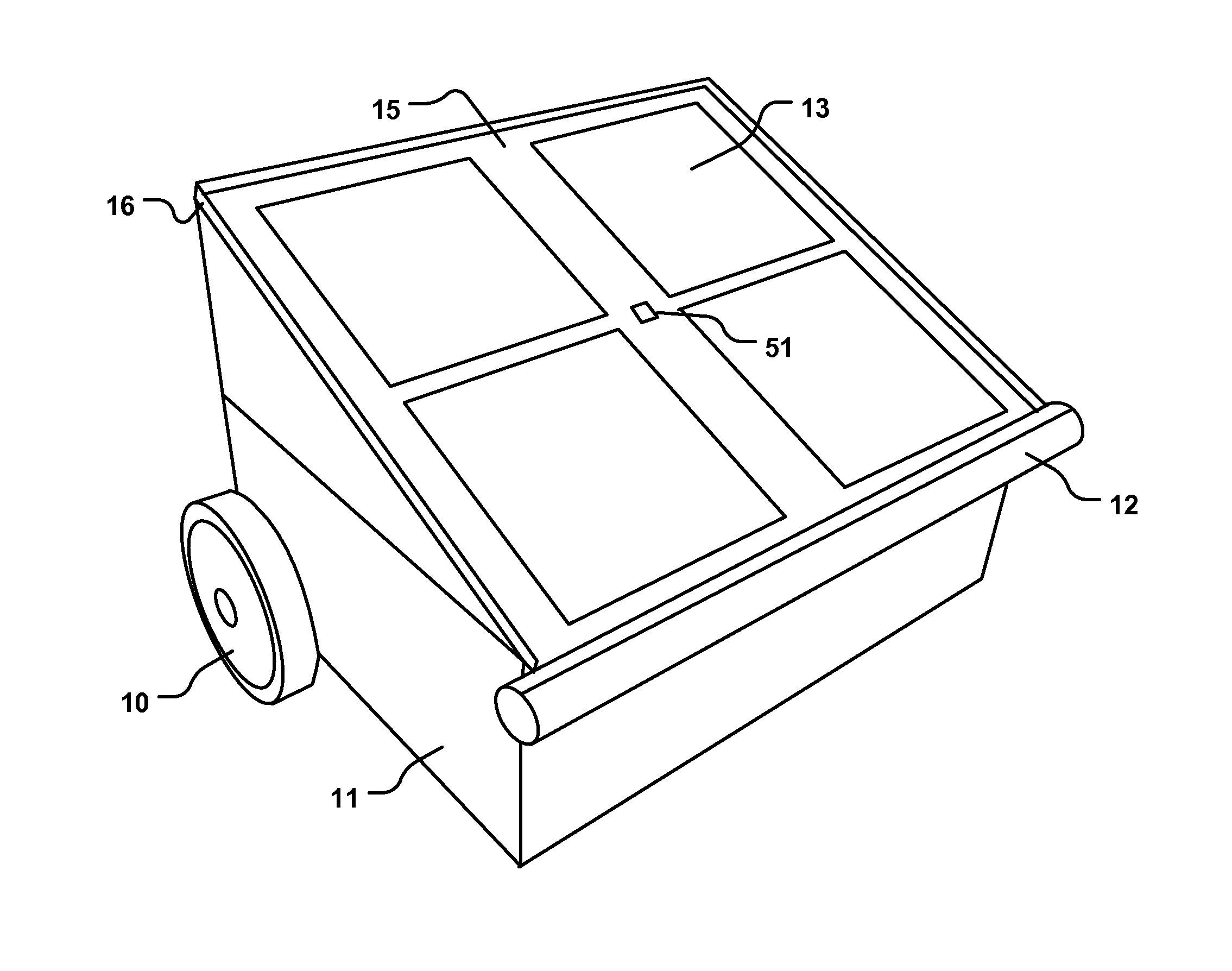
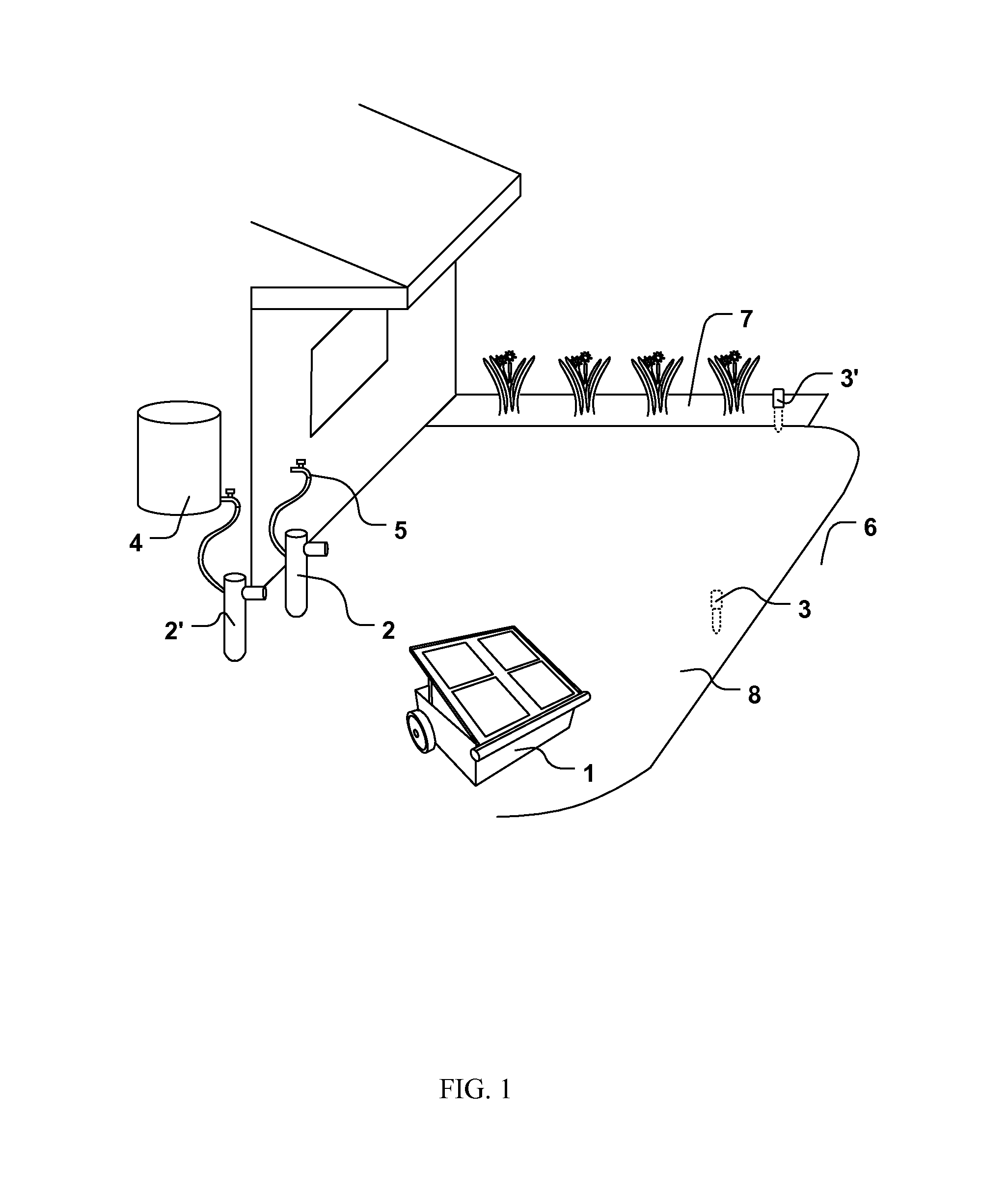
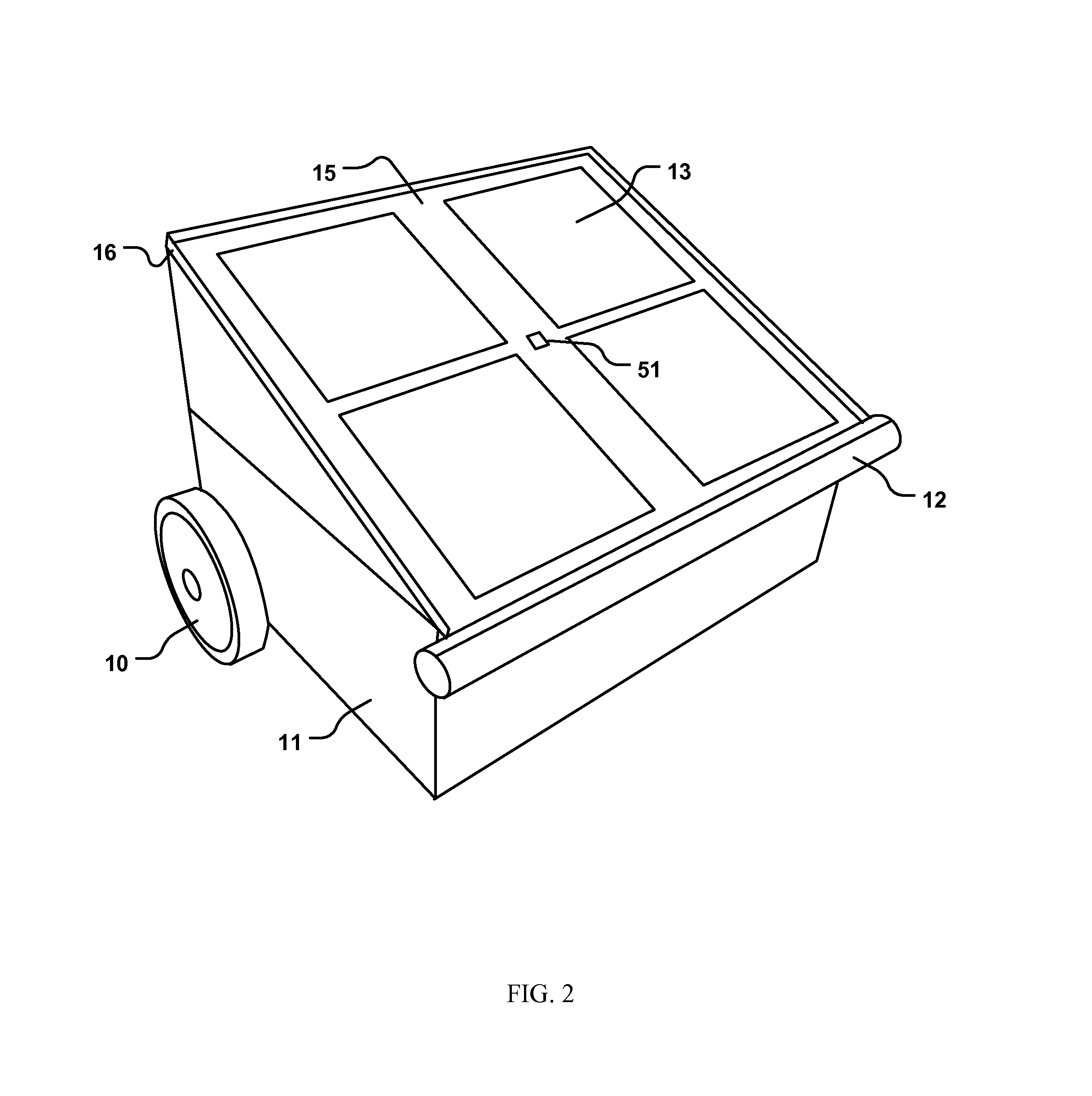
[0033]With reference to FIG. 3, in certain embodiments the system comprises a mobile robot 1 (an irrigator) with an autonomous navigation system, control module 33 and an integral water tank 24. With reference to FIG. 1, the robot 1 autonomously fills the water tank from a refill station 2, tra...


PUM


Abstract

A device for irrigating soil has a chassis having wheels or tracks for motion, the chassis having one or more water sprinklers with streams directed at the soil, a water storage tank, and a sloped catchment surface having one or more sloped planes or curved surfaces for receiving water from a refill station into the water storage tank, wherein, under the control of an electronic circuit, the irrigation device can refill the water tank by positioning any part of the catchment surface under a water stream from the refill station. A method has the steps of measuring soil moisture at remote locations, refilling the mobile robot using a gravity feed water stream, defining a route for distribution of water, traversing the irrigation routes, refilling water according to soil moisture measurements, storing photovoltaic energy in a battery, and rotating, to a compass heading such that the photovoltaic array is optimally oriented.

Description

CROSS-REFERENCES TO RELATED APPLICATIONS[0001]The current application claims the benefit of two earlier-filed provisional patent applications.[0002]The first provisional patent application was filed on Jun. 17, 2014 and was assigned application Ser. No. 62 / 013,054 It listed the same inventor.[0003]The second provisional patent application was filed on Feb. 16, 2015 and was assigned application Ser. No. 62 / 116,883. It listed the same inventor.BACKGROUND [0004]1. Field of the Invention[0005]The invention relates to a device and a method for irrigation areas of ground, specifically to an improved mobile irrigation device and method.[0006]2. Description of Related Art[0007]Efficient irrigation requires the delivery of water to planted areas such that water waste due to evaporating, distribution to paved areas, leaks, under-watering, and over-watering is minimized. Irrigation is further complicated because water requirements and moisture levels vary even over a few feet of distance withi...

Claims


Application Information

Patent Timeline
Patent Type & Authority Applications(United States)
IPC IPC(8): A01G25/09G05D1/00A01G25/16
CPCA01G25/09G05D1/0088A01G25/167G05D1/0246G05D1/0261G05D1/027G05D2201/0201Y02P60/12
Inventor GUY, JONATHAN
Owner GUY JONATHAN
Why Eureka
Try Eureka