
Hydraulic auxiliary brake device of motor used for oil production

a technology of hydraulic auxiliary brake and oil production motor, which is applied in the direction of liquid resistance brakes, mechanical equipment, and wellbore/well accessories, etc., can solve the problems of reverse turning of the turning shaft and the oil extraction pump, flow reverse, and equipment parse revers

Active Publication Date: 2015-12-17
WONG YEN HONG
View PDF9 Cites 13 Cited by
  • Summary
  • Abstract
  • Description
  • Claims
  • Application Information

AI Technical Summary

Benefits of technology

The present invention provides a motor with a hydraulic auxiliary brake device that prevents the turning shaft from reversely turning in case of power failure. The device includes a turning shaft, a brake disc, a hydraulic brake, a one-way clutch gear, an oil pump, and an oil pressure pipe. When the turning shaft is turned normally for oil production, the oil pump doesn't output oil pressure, and the hydraulic brake doesn't activate. However, if the turning shaft is reversely turned due to power failure, the oil pump is opened to output oil pressure, and the hydraulic brake is activated to brake the brake disc, preventing the turning shaft from reversely turning. This improves the safety of the motor and ensures efficient braking in emergency situations.

Problems solved by technology

Hence, in case of a power failure, the turning shaft and the oil extraction pump which are very long (about thousands of meters) will a counterforce when they are stopped turning, which causes a reverse turning of the turning shaft and the oil extraction pump.
The reverse tuning will cause the petroleum to flow reversely and the pars of the equipment to turn reversely and to cause damages accordingly.
Thus, the conventional motor is unable to brake the turning shaft and the oil extraction pump instantaneously in case of a power failure to result in a reverse turning.

Method used


Image

  • Hydraulic auxiliary brake device of motor used for oil production
  • Hydraulic auxiliary brake device of motor used for oil production
  • Hydraulic auxiliary brake device of motor used for oil production

Examples


Embodiment Construction

[0008]Embodiments of the present invention will now be described, by way of example only, with reference to the accompanying drawings.

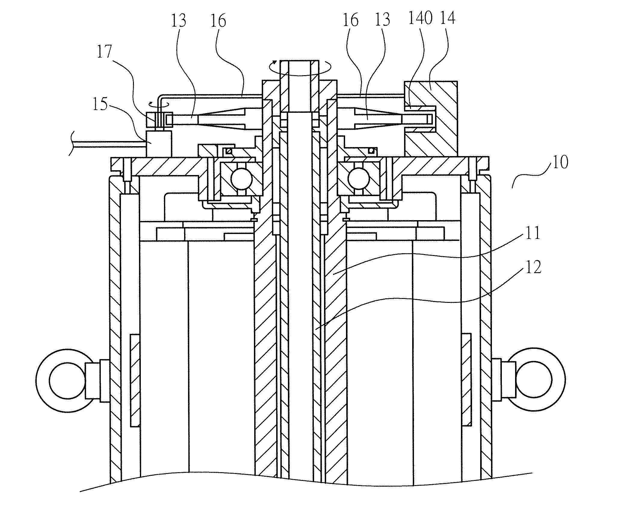
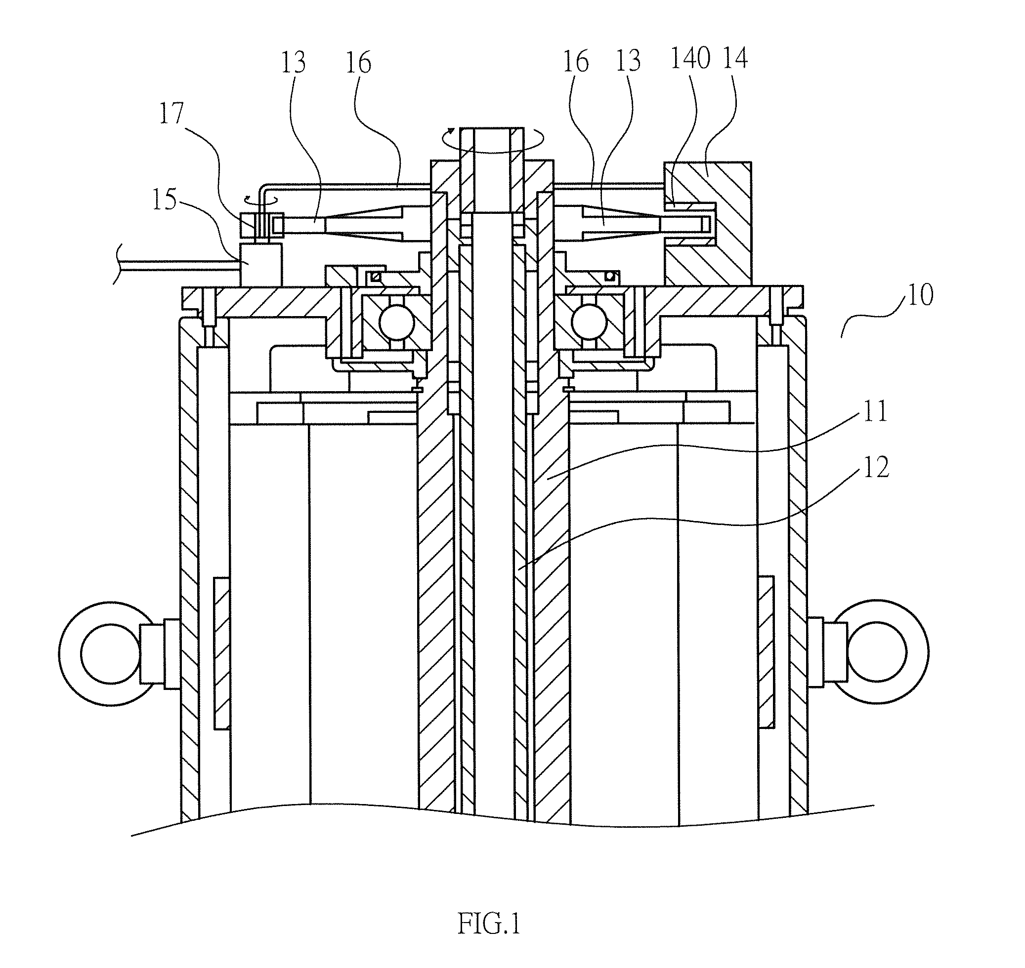
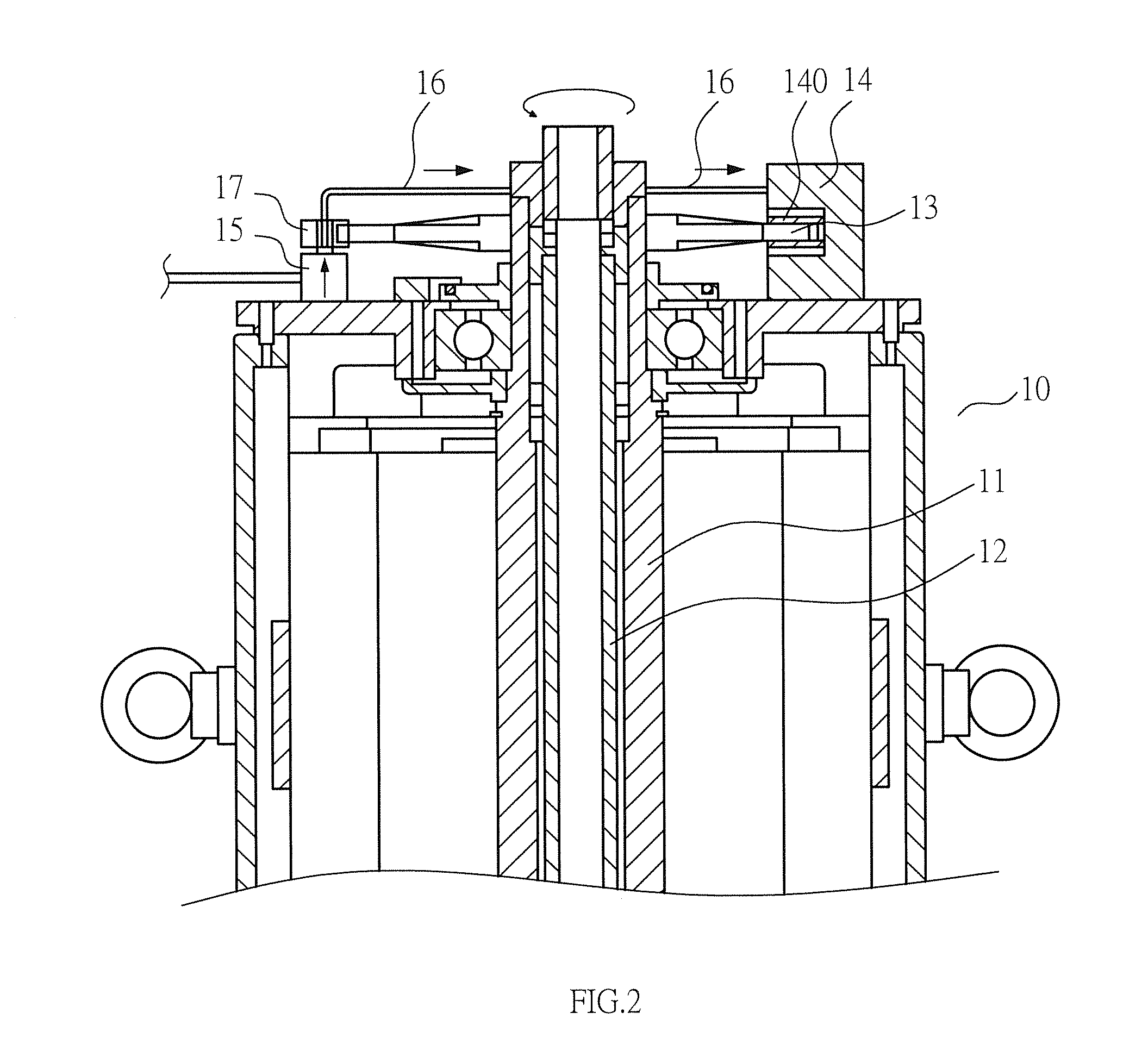
[0009]Referring to FIG. 1, a motor 10 has a turning shaft 11 and an oil extraction pump 12 which are integrally linked. The turning shaft 11 is coupled with a brake disc 13. One side of the brake disc 13 is provided with a hydraulic brake 14. The hydraulic brake 14 has a brake caliper 140 corresponding to the brake disc 13. Another side of the brake disc 13 is provided with an oil pump 15. The oil pump 15 is adapted to output oil pressure. The switch valve of the oil pump 15 is connected with a one-way clutch gear 17. The one-way clutch gear 17 meshes with the brake disc 13. The oil pump 15 is provided with an oil pressure pipe 16 connected to the hydraulic brake 14.

[0010]According to the aforesaid device and structure, the function and effect of the present invention are described hereinafter. When the motor 10 is turned under the normal power supply...


PUM


Abstract

A hydraulic auxiliary brake device of a motor used for oil production is provided. A turning shaft and an oil extraction pump of the motor are provided with a brake disc. The motor is provided with a hydraulic brake. The hydraulic brake is connected with an oil pressure pipe, a one-way clutch gear, and an oil pump. The one-way clutch gear meshes with the brake disc. When the turning shaft and the oil extraction pump of the motor are turned normally for oil production, the one-way clutch idles so that the oil pump doesn't output oil pressure, and the hydraulic brake doesn't activate to brake the brake disc. In case of a power failure, the oil pump is opened to output oil pressure and the hydraulic brake is activated to brake the brake disc, such that the turning shaft and the oil extraction pump are stopped from turning.

Description

BACKGROUND OF THE INVENTION[0001]1. Field of the Invention[0002]The present invention relates to a hydraulic auxiliary brake device of a motor used for oil production, and more particularly to a hydraulic auxiliary brake device having a hydraulic brake to prevent a reverse turning from causing damages in case of a power failure.[0003]2. Description of the Prior Art[0004]A conventional spiral rod motor used for oil production has a long hollow turning shaft and an oil extraction pump to extending into an oil field underground. The turning shaft and the spiral oil extraction pump are turned to extract the petroleum underground. The conventional spiral rod motor doesn't have a brake device. Hence, in case of a power failure, the turning shaft and the oil extraction pump which are very long (about thousands of meters) will a counterforce when they are stopped turning, which causes a reverse turning of the turning shaft and the oil extraction pump. The reverse tuning will cause the petro...

Claims


Application Information

Patent Timeline
Patent Type & Authority Applications(United States)
IPC IPC(8): F16D67/04F16D55/225
CPCF16D55/225F16D67/04F16D2127/004F16D55/22E21B43/126F16D57/002
Inventor SHEN, KUEI-HSIEN
Owner WONG YEN HONG
Learn More