Distance-measuring-device

a technology of distance measurement and distance, applied in distance measurement, instruments, surveying and navigation, etc., can solve the problem that digital parameters do not accurately represent what is actually emitted in the air, and achieve the effect of accurately determining the distance of an obj

Active Publication Date: 2015-12-17
APTIV TECH LTD
View PDF2 Cites 21 Cited by
  • Summary
  • Abstract
  • Description
  • Claims
  • Application Information

AI Technical Summary

Benefits of technology

[0006]It is an object of the invention to provide an improved distance-measuring-device and associated method for doing the same in order to overcome such problems...

Problems solved by technology

These digital parameters do not accurately represent what is really emitted in the air, because of the...

Method used


Image

  • Distance-measuring-device
  • Distance-measuring-device
  • Distance-measuring-device

Examples


example method 1

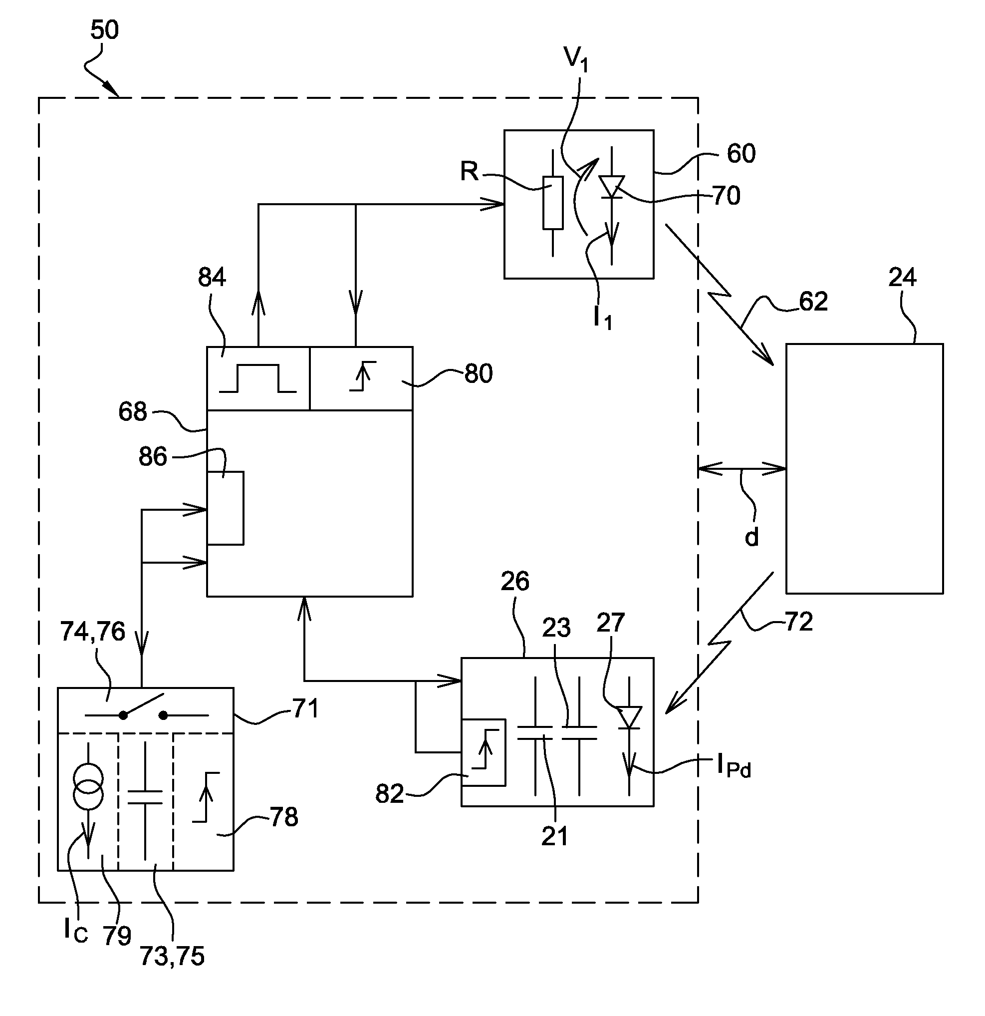
[0051]FIG. 5 shows an example of timing charts of signals processed by the distance-measuring-device 50 according to one implementation of the methodology.

[0052]A first timing chart B1 shows the characteristics of the emitted light-pulse 62 and specifically shows the current I1 flowing through the optical diode 70 during the emission of the emitted light-pulse 62. The form of the current I1 includes a smooth rising edge RE and a smooth falling edge FE. The smooth rising edge RE corresponds to the transient during activation of the gate driver of the light-emitting component 60, excited by the sharp rising edge of the digital pulse generated by the signal generator 84. The smooth falling edge FE corresponds to the transient during deactivation of the gate driver of the light-emitting component 60 excited by the sharp falling edge of the digital pulse generated by the signal generator 84.

[0053]A reference time T0 is shown when the level of the current I1 of the optical diode 70 exceed...

example method 2

[0068]A fifth timing chart B5 shows an alternative method. The ‘Y’ axis is a representation of the activation of the time slots (TS1, TS2). The method integrates the current Ipd starting at the time TA that depends on the point the second adjustable threshold voltage THL2 is achieved and ends at the time TB. The photosensitive element 27 starts to generate the current Ipd at the time TA and ends to generate the current Ipd at the time TB, i.e. the reflected light-pulse 72 starts to influence the photosensitive element 27 at the time TA and stops at the time TB. The current Ipd is integrated during the first and the second time slots TS1, TS2 that results respectively to a third and a fourth amount of electrical charges Q3, Q4.

[0069]The distance d to the object 24 can be calculated by using Eq. 7 where c stands for the velocity of light in the medium through which it propagates:

d=½*c*ΔT1*(Q3 / (Q3+Q4)).  Eq. 7.

[0070]In order to implement this with the apparatus of FIG. 3, the first cap...


PUM


Abstract

An apparatus and method for determining the distance from a distance-measuring-device to an object by sending a light-pulse from a light-emitting component toward the object by passing a current pulse through the component. A value based on the current or voltage across the component is used to determine the reference-time T0 when the value exceeds a first threshold-value, and determines first-time T1 when the value is reduced to a second threshold-value THL2. T1 is used to define two time-windows when intensity of reflected light is integrated to provide two values (Q1/Q3 and Q2/Q4) to determine a time of flight for the light-pulse based on the two values (Q1/Q3 and Q2/Q4), the difference between T0 and T1 (T1-T0), and the speed of light, c.

Description

CROSS-REFERENCE TO RELATED APPLICATION[0001]This application claims the benefit under 35 U.S.C. §119(a) of European Patent Application EP 14172114.2, filed 12 Jun. 2014, the entire disclosure of which is hereby incorporated herein by reference.TECHNICAL FIELD OF INVENTION[0002]This disclosure relates to a distance-measuring-device determining a distance of an object from the distance-measuring-device and its associated method for doing the same.BACKGROUND OF INVENTION[0003]One method of distance-measuring-devices is the measurement of the distance to an object by determining the time of flight of a light pulse. It is known in the art to provide distance-measuring-devices which send a precisely timed light pulse toward an object and to make gated measurements of the light reflected thereby. The time of flight of the light pulse is simply related to the range of the object through the relation d=c*Δtd / 2, where d is the distance to the object, c stands for the velocity of light in the ...

Claims


Application Information

Patent Timeline
IPC IPC(8): G01S7/486G01S17/08G01S7/4865G01S17/10G01S17/894
CPCG01S17/08G01S7/4865G01S17/10G01S7/484G01S7/497G01S17/894
Inventor HEINRICH, MARKUS
Owner APTIV TECH LTD
Why Eureka
Try Eureka