Antireflection coating and optical element including the same
- Summary
- Abstract
- Description
- Claims
- Application Information
AI Technical Summary
Benefits of technology
Problems solved by technology
Method used
Image

Examples
example 2
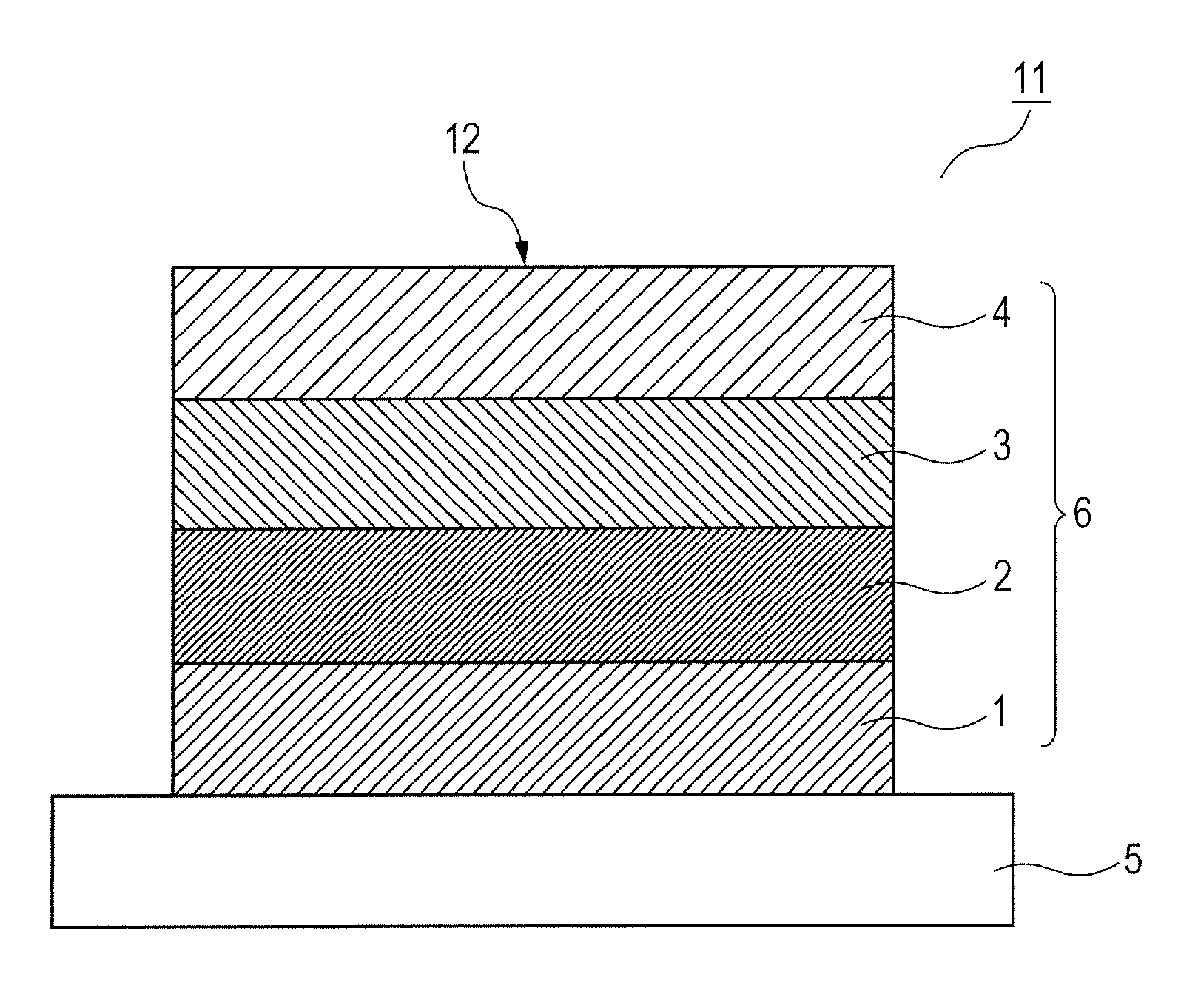
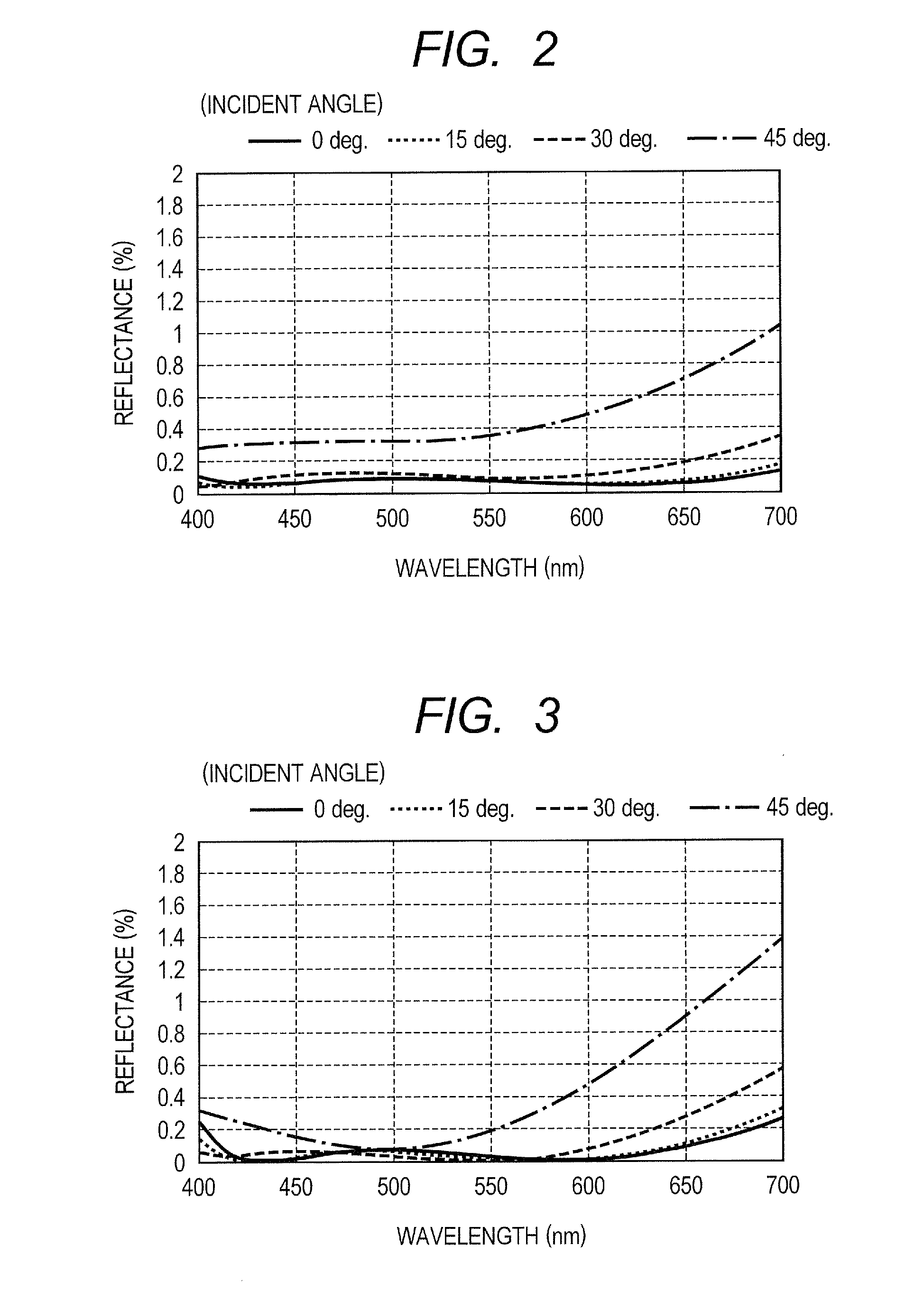
[0043]In Example 2, on a substrate of the trade name of S-LAH65v (OHARA INC., trade name, the refractive index of the material is 1.81 (wavelength λ=550 nm)), an antireflection coating having the construction shown in FIG. 1 was produced so as to have a film construction shown in Table 2. On this occasion, the first layer 1 to the third layer 3 were formed by the vacuum deposition method. The main component of the first layer 1 was MgF2, the main component of the second layer 2 was Ta2O5, and the main component of the third layer 3 was Al2O3. For the fourth layer 4, a binder solution was added to a hollow MgF2-containing solution such that the refractive index for wavelength λ=550 nm became 1.20, the coating with the mixed and prepared liquid was performed by the spin coater, and the baking was performed by the clean oven at 100 to 250° C. for one hour.
[0044]FIG. 3 illustrates the reflectance characteristics at incident angles of 0 degrees, 15 degrees, 30 degrees and 45 degrees, in ...
example 3
[0045]In Example 3, on a substrate of the trade name of S-LAH79 (OHARA INC., trade name, the refractive index of the material is 2.01 (wavelength λ=550 nm)), an antireflection coating having the construction shown in FIG. 1 was produced so as to have a film construction shown in Table 3. The first layer 1 to the third layer 3 were formed by the vacuum deposition method. For the fourth layer 4, the coating with a hollow SiO2 mixed and prepared liquid was performed by the spin coater, and thereafter, the film formation was performed by a one-hour baking. The main component of the first layer 1 was SiO2, the main component of the second layer 2 was Ta2O5, and the main component of the third layer 3 was Al2O3.
[0046]FIG. 4 illustrates the reflectance characteristics at incident angles of 0 degrees, 15 degrees, 30 degrees and 45 degrees, in a wavelength range of 400 nm to 700 nm. In the antireflection coating according to the example, in the wavelength range of 400 nm to 700 nm, the maxim...
example 4
[0047]In Example 4, on a substrate of the trade name of S-LAH79 (OHARA INC., trade name, the refractive index of the material is 2.01 (wavelength λ=550 nm)), an antireflection coating having the construction shown in FIG. 1 was produced so as to have a film construction shown in Table 4. The first layer 1 to the third layer 3 were formed by the vacuum deposition method. For the fourth layer 4, the coating with a hollow SiO2 mixed and prepared liquid was performed by the spin coater, and thereafter, the film formation was performed by a one-hour baking. The main components of the first layer 1 and the third layer 3 were Al2O3, and the main component of the second layer 2 was Ta2O5.
[0048]FIG. 5 illustrates the reflectance characteristics at incident angles of 0 degrees, 15 degrees, 30 degrees and 45 degrees, in a wavelength range of 400 nm to 700 nm. In the antireflection coating according to the example, in the wavelength range of 400 nm to 700 nm, the maximum value of the reflectanc...
PUM
 Abstract
Description
Claims
Application Information
 - R&D Engineer
- R&D Manager
- IP Professional
- Industry Leading Data Capabilities
- Powerful AI technology
- Patent DNA Extraction
Browse by: Latest US Patents, China's latest patents, Technical Efficacy Thesaurus, Application Domain, Technology Topic.
© 2024 PatSnap. All rights reserved.Legal|Privacy policy|Modern Slavery Act Transparency Statement|Sitemap