
Projection screen and manufacturing method of projection screen

a technology of projection screen and manufacturing method, which is applied in the field of optical devices, can solve the problems of significant reduction of energy utilization efficiency and significant difficulty in aligning front and rear surfaces of projection screen in the manufacturing process of projection screen, and achieve the effect of increasing brightness gain and enhancing image contras

Active Publication Date: 2015-12-17
NANO PRECISION TAIWAN LTD
View PDF5 Cites 8 Cited by
  • Summary
  • Abstract
  • Description
  • Claims
  • Application Information

AI Technical Summary

Benefits of technology

This patent describes a projection screen that can make images brighter and clearer. The method of manufacturing the screen is also described in the patent. The technical effects of this invention are to enhance image contrast and increase brightness gain of the projection screen.

Problems solved by technology

However, the difficulty in aligning front and rear surfaces of the projection screen significantly complicates the manufacturing process of projection screen.
In addition, conventional light absorption layers excessively absorb the projection beams, such that energy utilization efficiency is unavoidably reduced.

Method used


Image

  • Projection screen and manufacturing method of projection screen
  • Projection screen and manufacturing method of projection screen
  • Projection screen and manufacturing method of projection screen

Examples


Embodiment Construction

[0040]In the following detailed description of the preferred embodiments, reference is made to the accompanying drawings which form a part hereof, and in which are shown by way of illustration specific embodiments in which the invention may be practiced. In this regard, directional terminology, such as “top,”“bottom,”“front,”“back,” etc., is used with reference to the orientation of the Figure(s) being described. The components of the invention could be positioned in a number of different orientations. As such, the directional terminology is used for purposes of illustration and is in no way limiting. On the other hand, the drawings are only schematic and the sizes of components may be exaggerated for clarity. It is to be understood that other embodiments may be utilized and structural changes may be made without departing from the scope of the invention. Also, it is to be understood that the phraseology and terminology used herein are for the purpose of description and should not b...


PUM

PropertyMeasurementUnit
transparentaaaaaaaaaa
focal lengthaaaaaaaaaa
widthaaaaaaaaaa

Abstract

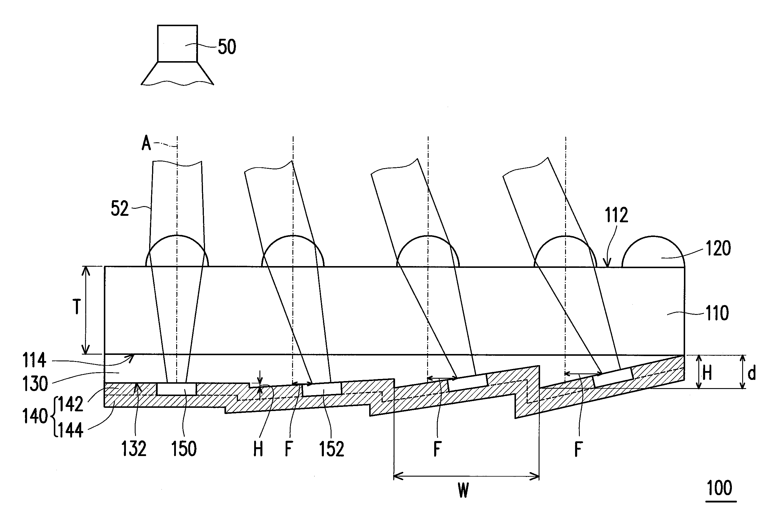
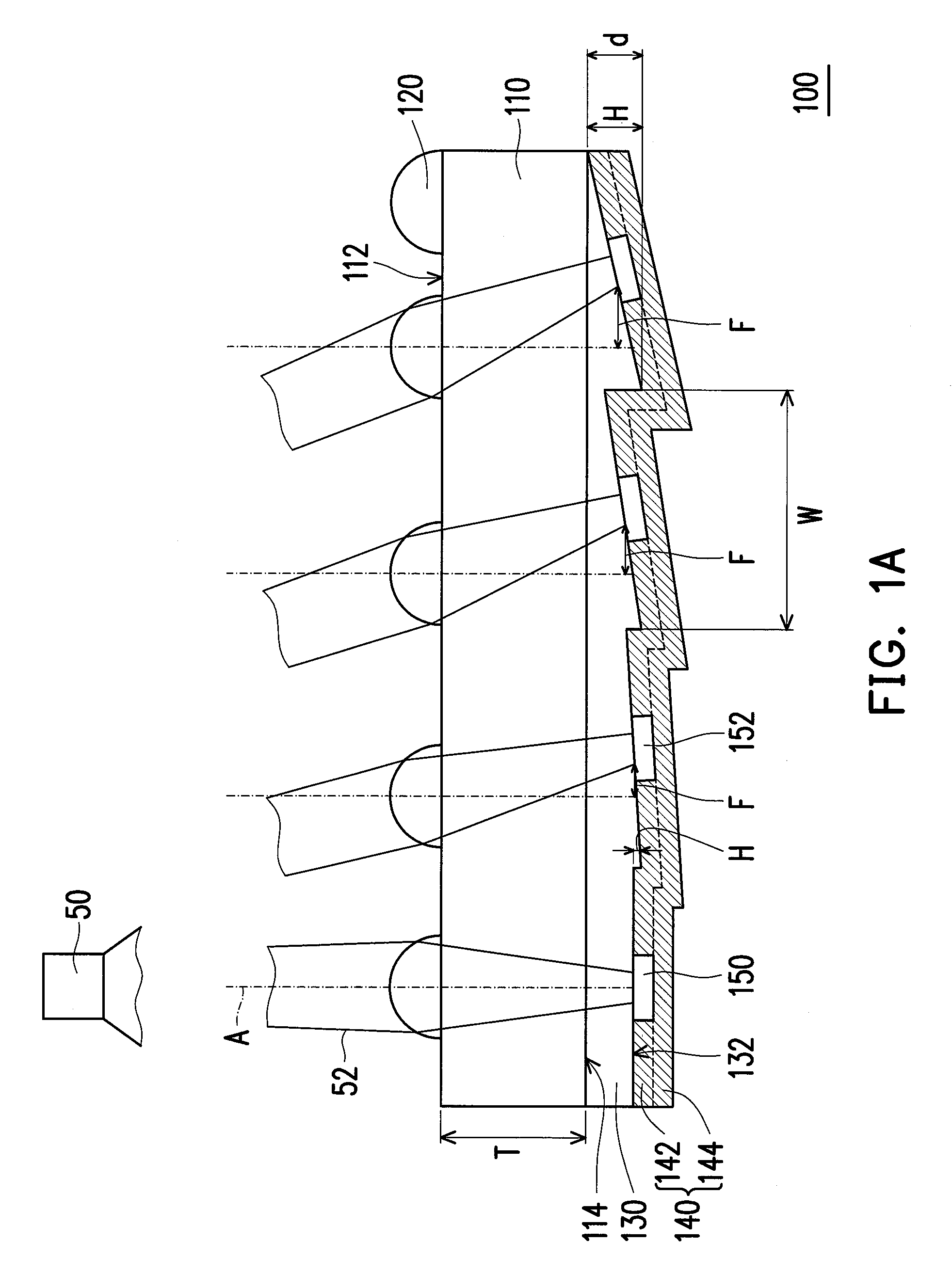
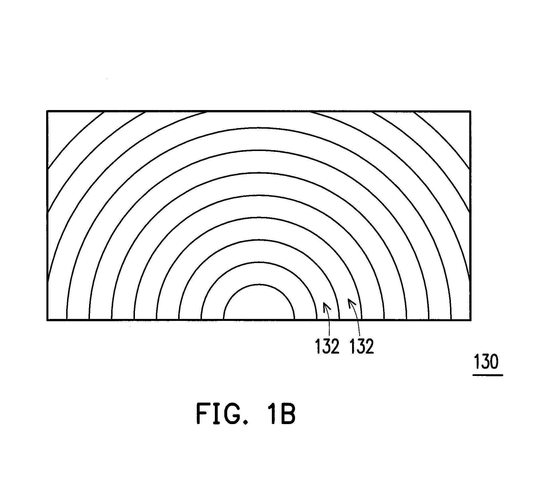
A projection screen that includes a transparent substrate, a plurality of micro-lens structures, a Fresnel lens structure, a light absorption layer, and a diffusive reflection layer is provided. The transparent substrate has a first surface and a second surface opposite to the first surface. The micro-lens structures are located at the first surface of the transparent substrate. The Fresnel lens structure is located at the second surface of the transparent substrate. The light absorption layer includes a light absorption portion. The diffusive reflection layer includes a plurality of dispersive diffusive reflection portions connected to the Fresnel lens structure. The deviation degrees of the diffusive reflection portions with respect to a plurality of optical axes of the corresponding micro-lens structures increase together with an increase in slopes of inclined surfaces of the Fresnel lens structure on the corresponding optical axes. A manufacturing method of the projection screen is also provided.

Description

CROSS-REFERENCE TO RELATED APPLICATION[0001]This application claims the priority benefit of Taiwan application serial no. 103120717, filed on Jun. 16, 2014. The entirety of the above-mentioned patent application is hereby incorporated by reference herein and made a part of this specification.BACKGROUND[0002]1. Field of the Disclosure[0003]The invention relates to an optical device and a manufacturing method thereof; more particularly, the invention relates to a projection screen and a manufacturing method thereof.[0004]2. Description of Related Art[0005]Micro-structures including inclined refraction / reflection surfaces for changing directions of beams, a micro-lens array for converging beams, a diffusive structure for scattering projection beams, and a light absorption structure for absorbing ambient beams may be configured on a projection screen.[0006]However, the difficulty in aligning front and rear surfaces of the projection screen significantly complicates the manufacturing pro...

Claims


Application Information

Patent Timeline
Patent Type & Authority Applications(United States)
IPC IPC(8): G03B21/602G03F7/00G02B3/00G02B3/08G02B5/02G02B5/00G03B21/60
CPCG03B21/602G02B5/0284G03F7/0005G02B3/0006G02B3/08G02B5/003G02B5/09
Inventor CHUANG, FU-MINGCHIEN, HUNG-TASU, FANG-HSUAN
Owner NANO PRECISION TAIWAN LTD
Learn More