Load driving circuit

Inactive Publication Date: 2015-12-17
FUJI ELECTRIC CO LTD
View PDF7 Cites 14 Cited by
  • Summary
  • Abstract
  • Description
  • Claims
  • Application Information

AI Technical Summary

Benefits of technology

[0012]This enables the short circuit detection circuit to immediately transmit the rising of the voltage at the output terminal of the load driving circuit to the output side thereof through the capacitor. Thus, the control signal for releasing the clamping operation can be outputted to the clamping circuit with immediate rising to enable an immediate clamp releasing operation. Therefore, in a normal switching operation, the load driving circuit can be prevented from such a malfunction as to incorrectly detect a state with a delay in the detection of the rising of the output voltage in a normal switching operation as a load short circuit state and shift the operation mode into an o

Problems solved by technology

In output current control performed by the duty factor control, when an object driven by a linear solenoid (a transmission of a vehicle, for example) is excessively loaded to cause a resulting switching operation of the linear solenoid to be carried out with a current up to a large current region, a short circuit failure sometimes occurs in the linear solenoid as the inductive load.
This causes the presence of the action of the clamping operation by the current limiting section.
In such a load driving circuit, however, when the level of a load current at the normal switching operation is close to the overcurrent detection level at a load short circuit, some operating conditions (power supply voltages, temperatures etc.) cause the rising of the output voltage to slow down to make the output voltage come to be left hard to rise.
As a result, there was a problem of causing such a continuous abnormality processing mode that the current limiting section incorrectly detects that there has been a load short circuit and outputs an oscillating waveform from the output terminal.
However, there was also such a problem that excessive reduction of the impedance in the portion of the circuit for clamping further inhibits the rising of an output voltage at the normal switching operation to cause problems such as waveform distortion and an increase in turning-on time.

Method used


Image

  • Load driving circuit
  • Load driving circuit
  • Load driving circuit

Examples


Example

[0022]In the following, an embodiment of the invention will be explained in detail with reference to attached drawings.

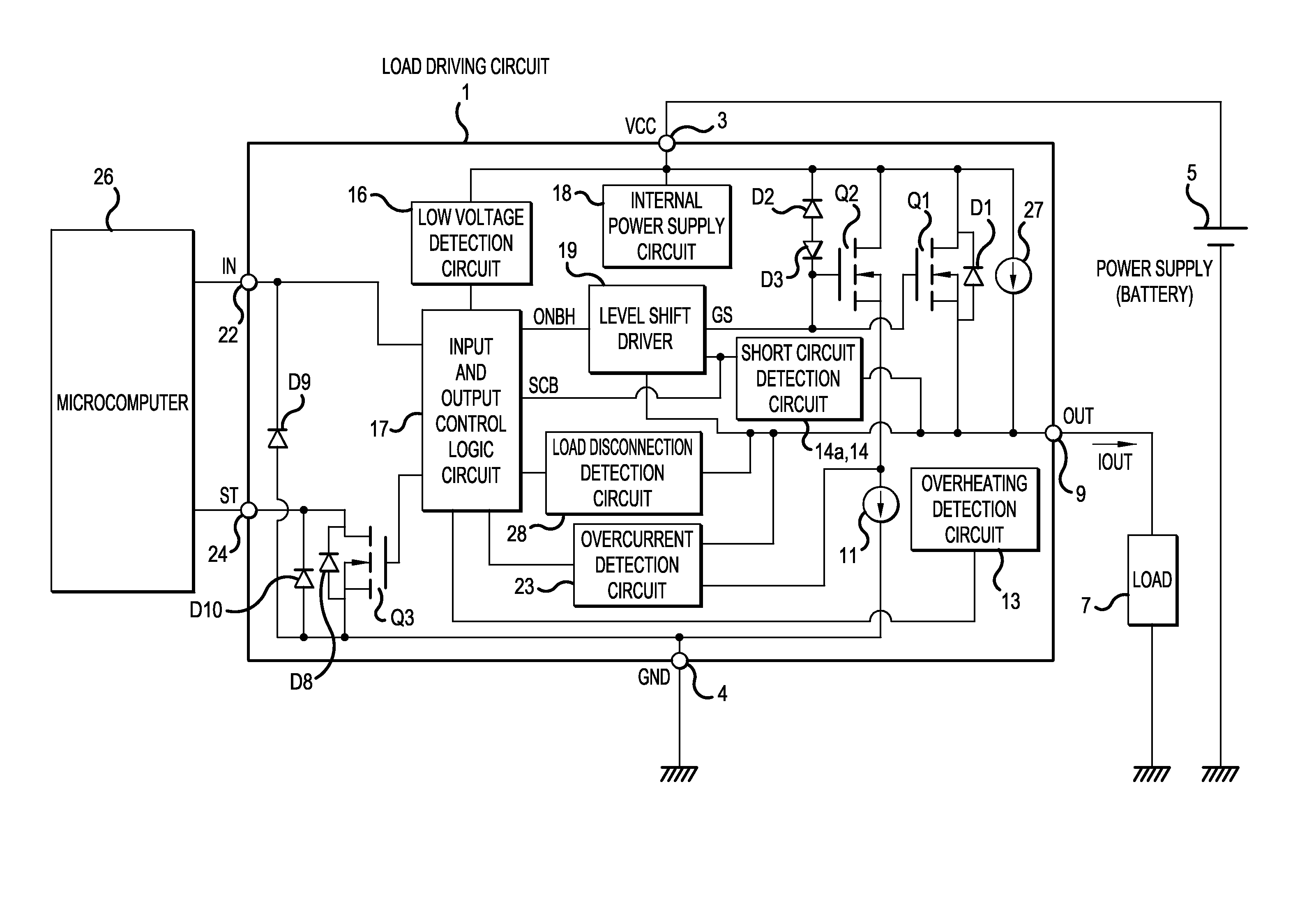
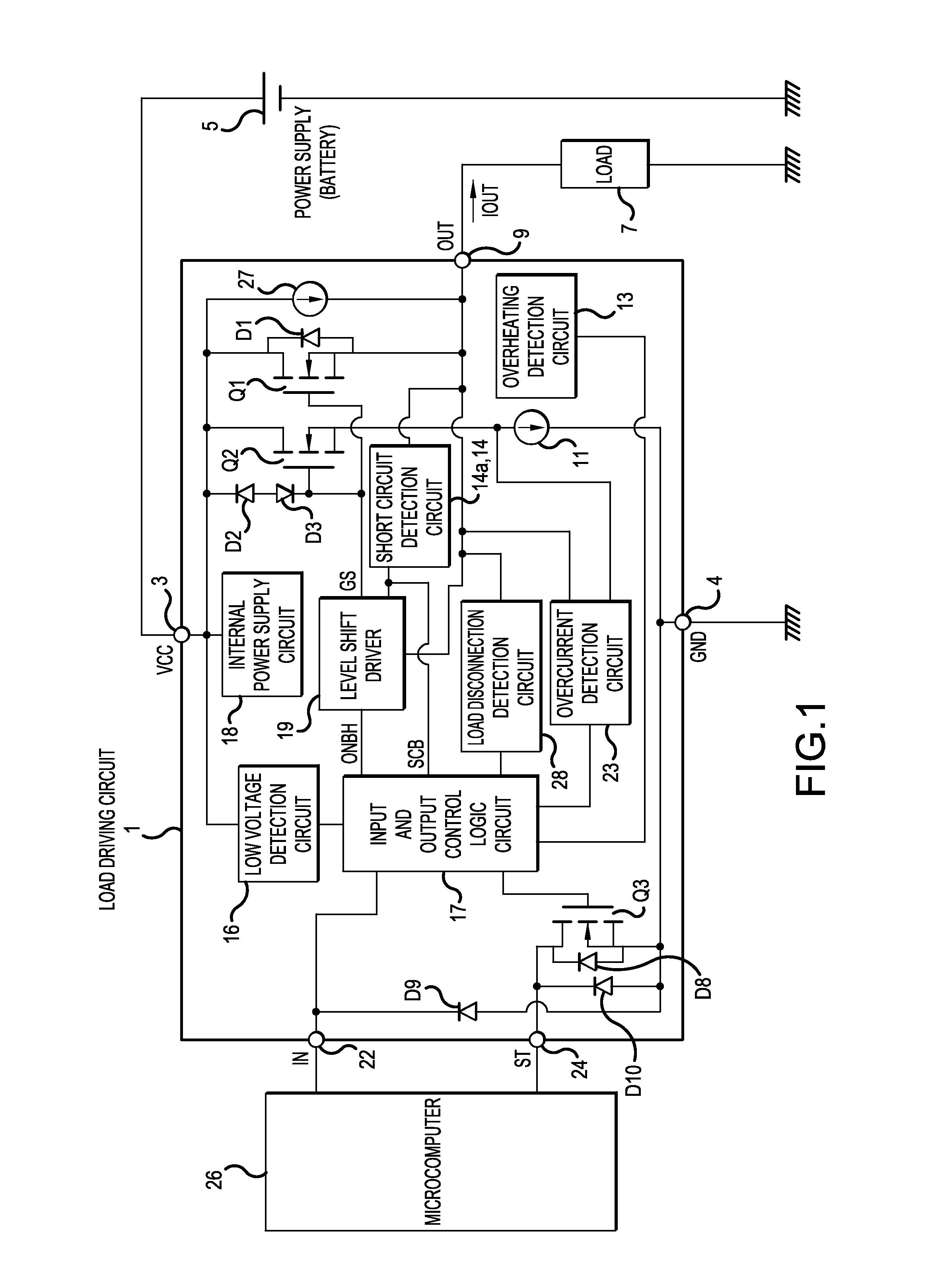
[0023]FIG. 1 is a block diagram showing an example of the configuration of a load driving circuit according to an embodiment of the invention.

[0024]The load driving circuit 1 has a VCC terminal 3 as a power supply terminal supplying a power supply voltage VCC, a GND terminal 4 as a grounding terminal, and an OUT terminal 9 as an output terminal. To the VCC terminal 3, the positive electrode of a power supply (battery) 5 is connected and to the OUT terminal 9, one end of a load 7 is connected. All of the negative electrode of the power supply 5, the other end of the load 7 and the GND terminal 4 are grounded.

[0025]In the load driving circuit 1, between the VCC terminal 3 and the OUT terminal 9, a switching device Q1 of an n-channel MOSFET (Metal-Oxide-Semiconductor Field-Effect Transistor) is provided. A diode D1 connected in inverse-parallel to the switching device ...


PUM


Abstract

A short circuit detection circuit has an output voltage of a switching device inputted and, when the value of the output voltage becomes lower than a specified threshold value due to an abnormal state such as a load short circuit state, outputs a control signal to a clamping circuit for making the clamping circuit carry out such a clamping operation as to limit the output current of the switching device. When the output voltage rises again by the turning-on operation of the switching device, the change in the output voltage is transmitted onto the output side through a capacitor with following rising in the control signal, by which the rising of the output signal is detected with little delay.

Description

BACKGROUND OF INVENTION[0001]1. Field of the Invention[0002]Embodiments of the invention relates to load driving circuits, and particularly to a load driving circuits having a function of detecting a load short circuit.[0003]2. Related Art[0004]In a load driving circuit with a so-called high-side configuration having a switching device provided between the positive electrode of a power supply and a load, when the load driving circuit particularly drives an inductive load such as a linear solenoid, an output current is controlled by duty factor control. In output current control performed by the duty factor control, when an object driven by a linear solenoid (a transmission of a vehicle, for example) is excessively loaded to cause a resulting switching operation of the linear solenoid to be carried out with a current up to a large current region, a short circuit failure sometimes occurs in the linear solenoid as the inductive load.[0005]As circuits against such a short circuit, some ...

Claims


Application Information

Patent Timeline
IPC IPC(8): H02H9/02
CPCH02H9/025H02H1/0007
Inventor MINOYA, YOSHIAKI
Owner FUJI ELECTRIC CO LTD
Why Eureka
Try Eureka