
Inserts Having Geometrically Separate Materials for Slips on Downhole Tool

Active Publication Date: 2015-12-24
WEATHERFORD TECH HLDG LLC
View PDF3 Cites 25 Cited by
  • Summary
  • Abstract
  • Description
  • Claims
  • Application Information

AI Technical Summary

Benefits of technology

The patent text discusses the use of ceramic materials in tools used in drilling oil wells. Using ceramic materials can reduce the amount of metal used in the tool and make it easier to recycle after use. The inserts in the tool can be made of ceramic, cast iron, carbide, cermet, powdered metal, or a combination of these materials. Some of the inserts can also be made of materials that dissolve or degrade over time in response to certain conditions in the well.

Problems solved by technology

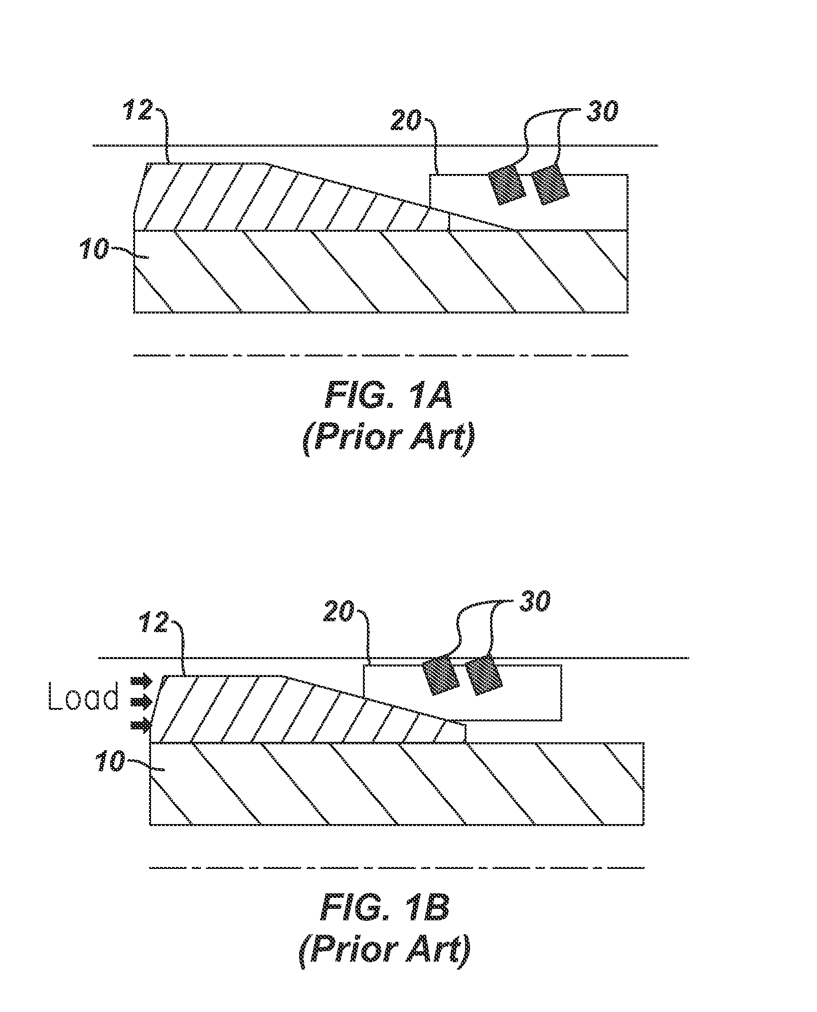
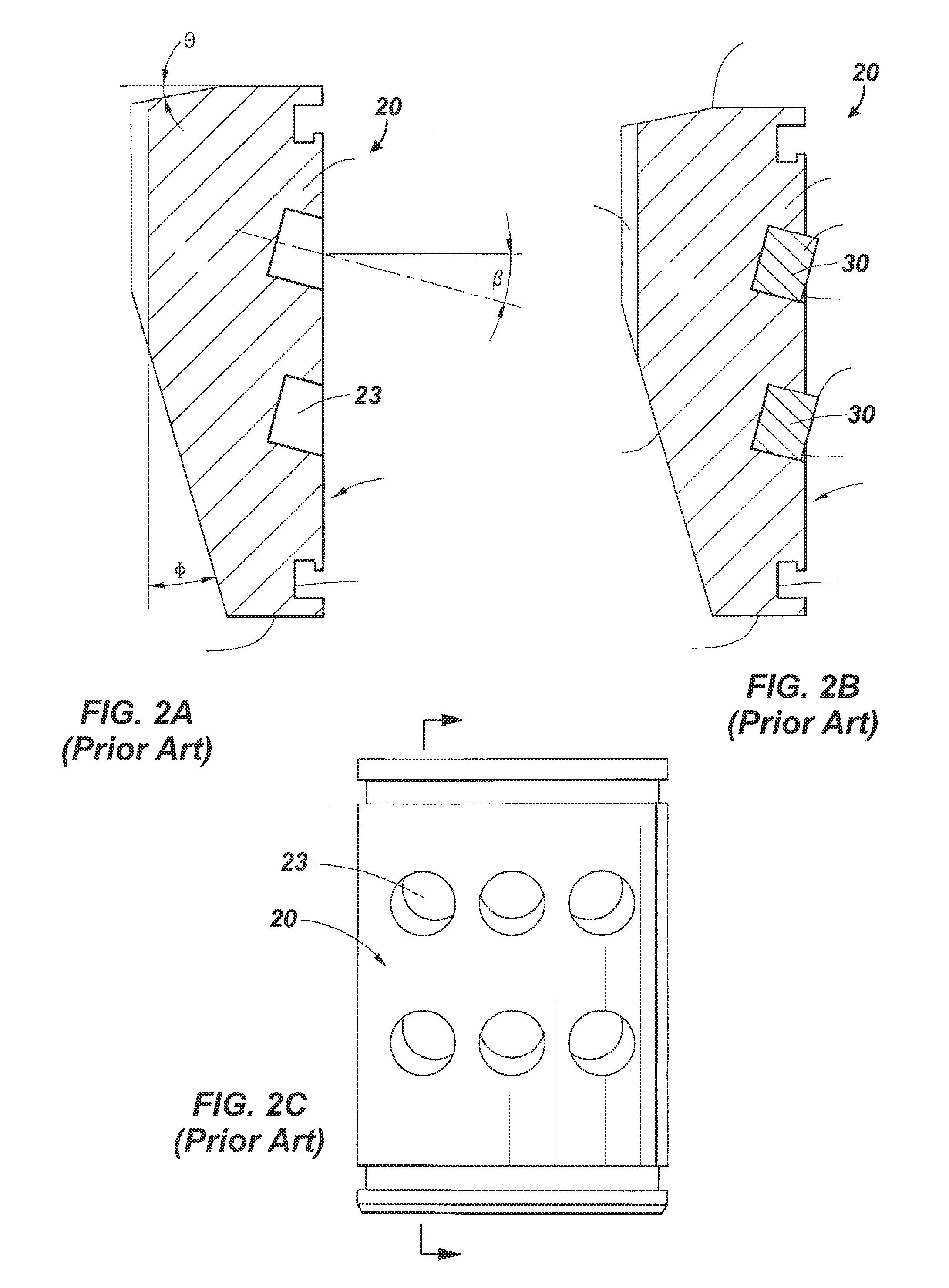
On non-metallic tools, such as composite plugs, the inserts can cause the non-metallic slips to fail when increased loads are applied.
Of course, when the slip fails, it disengages from the casing.
These metallic slips increase the metallic content of the plug and can cause issues during drill up in horizontal wells, especially when coil tubing is used during the milling operation.
Unfortunately, a large amount of metallic debris can still collect at the heel of the well and cause drill up problems when composite slips having inserts are used on tools.
In any event, when the downhole tool having slips with carbide inserts are milled out of the casing, the inserts tend to collect in the casing and are hard to float back to the surface.
In fact, in horizontal wells, the carbide inserts may tend to collect at the heel of the horizontal section and cause potential problems for operations.
Given that a well may have upwards of forty or fifty bridge plugs used during operations that are later milled out, a considerable number of carbide inserts may be left in the casing and difficult to remove from downhole.
Additionally, non-metallic buttons used to bite into the casing may tend to fracture due to loads applied onto them during the setting process.
This leads to a loss in structural integrity and inability to retain the position of the bridge plug in the well consistently.

Method used


Image

  • Inserts Having Geometrically Separate Materials for Slips on Downhole Tool
  • Inserts Having Geometrically Separate Materials for Slips on Downhole Tool
  • Inserts Having Geometrically Separate Materials for Slips on Downhole Tool

Examples


Embodiment Construction

[0032]FIG. 3 illustrates a downhole tool 100 in partial cross-section having slip assemblies 110U, 110D according to the present disclosure. The downhole tool 100 can be a bridge plug as shown, but it could also be a packer, a liner hanger, an anchoring device, or other downhole tool that uses a slip assembly to engage a downhole tubular, such as casing.

[0033]The tool 100 has a mandrel 102 having the slip assemblies 110U and 110D and backup rings 140 arranged on both sides of a packing element 150. Outside the inclined cones 112, the slip assemblies 110U and 110D have slips 120. Together, the slips 120 along with the cones 112 can be referred to as slip assemblies, or in other instances, just the slips 120 may be referred to as slip assemblies. In either case, either reference may be used interchangeably throughout the present disclosure. Thus, reference herein to a slip is not meant to refer only to one slip body, segment, or element, although it can. Instead, reference to slip can...


PUM


Abstract

A downhole tool, such as a fracture plug used during a fracture operation, installs in a downhole tubular, such as casing. The tool has a mandrel with a sealing element disposed thereon between uphole and downhole ends. Slip assemblies on the mandrel can be moved to engage the downhole tubular. When the tool is used as a bridge plug, the uphole assembly supports the sealing element compressed, and the downhole assembly supports fluid pressure downhole of the tool. The slip assemblies have inserts composed of at least two materials that are different from one another and are geometrically separate from one another. In addition or as an alternative, the slip assemblies can be composed of at least two different materials that are geometrically separate from one another.

Description

CROSS-REFERENCE TO RELATED APPLICATIONS[0001]This is non-provisional of U.S. Application Ser. No. 62 / 013,835 filed 18 Jun. 2014, which is incorporated herein by reference in its entirety and to which priority is claimed.BACKGROUND OF THE DISCLOSURE[0002]Slips are used for various downhole tools, such as bridge plugs and packers. The slips can have inserts or buttons to grip the inner wall of a casing or tubular. Inserts for slips are typically made from cast or forged metal, which is then machined and heat-treated to the proper engineering specifications according to conventional practices.[0003]Inserts for slips on metallic and non-metallic tools (e.g., packers, plugs, etc.) must be able to engage with the casing to stop the tools from moving during its operation. On non-metallic tools, such as composite plugs, the inserts can cause the non-metallic slips to fail when increased loads are applied. Of course, when the slip fails, it disengages from the casing. On non-metallic tools, ...

Claims


Application Information

Patent Timeline
IPC IPC(8): E21B23/01
CPCE21B23/01E21B33/129
Inventor MHASKAR, NAUMAN H.ROCHEN, JAMES A.YOUNG, JONATHAN A.
Owner WEATHERFORD TECH HLDG LLC
Learn More