Closed-cycle cryogenic engine and operating method for propelling vehicles and generating electricity

a closed-cycle, cryogenic engine technology, applied in machines/engines, natural sources of heating, lighting and heating apparatus, etc., can solve the problems of inability to use engines, impracticality, failure of previous attempts to harness natural heat energy and convert it into mechanical work with high power densities, etc., to extract a large amount of natural heat, the effect of huge propulsive power

Active Publication Date: 2015-12-24
MINOVITCH MICHAEL
View PDF0 Cites 9 Cited by
  • Summary
  • Abstract
  • Description
  • Claims
  • Application Information

AI Technical Summary

Benefits of technology

[0012]The thermally insulated high and low pressure gas storage cylinders are designed with variable volumes controlled by movable pistons that move in and out along their longitudinal central axis. Compressed sub-ambient gas is withdrawn from the high-pressure storage cylinder at some desired mass flow rate {dot over (m)}E and fed into the heat exchanger where it is heated. The heated compressed gas discharged from the heat exchanger is fed into the serially connected isentropic expanders where a large portion of the absorbed natural heat energy of the environment is converted into mechanical work at very high power densities that is inherent in high pressure cryogenic expanders. The expanded low pressure low temperature gas is fed into the low pressure storage cylinder where it is accumulated at the low pressure and sub-ambient temperature. This system of gas storage cylinders that are connected to the isothermal recompressor is designed to operate simultaneously or at different times whether the vehicle is moving or parked and not being used for transportation. This design feature of the invention enables the engine to use all the power generated by all of the cryogenic expanders to provide enormous propulsive power for propelling the vehicle over relatively long distances without evaporating any water. When the vehicle is parked and not being used for transportation, the engine is automatically turned on by an engine control computer to re-fill the high-pressure gas storage cylinder to maximum capacity by operating the recompressor. When the high-pressure cylinder is full, the engine control computer automatically turns the engine off.
[0013]The closed cycle operating principle of the cryogenic engine is achieved by isothermally compressing the gas (assumed to be hydrogen) to a very high initial pressure (assumed to be 600 Bar in the preferred embodiment) by absorbing the heat of compression by evaporating water at a sub-ambient temperature TL. Feeding it into the heat exchanger where it is isobarically heated to high temperature TH equal to the ambient temperature of the environment by extracting natural heat energy from the flowing atmospheric air at ambient temperature...

Problems solved by technology

Unfortunately, all prior attempts to harness this natural heat energy and convert it into mechanical work with high power densities by a closed cycle heat engine utilizing the natural environment as its high temperature heat reservoir have failed.
As a result of all of these unsuccessful attempts, thermodynamicists have concluded that such engines are impossible.
However, it is important to point out that this negative conclusion is not based on any fundamental physical law of nature but rather on the unsuccessful attempts to construct such engines.
Unfortunately, all prior attempts have been impractical because they have very low power densities.
The engine can only continue to operate by continuously feeding in new liquified gas at cryogenic temperature into the compressor.
831-837 by M. V. Sussman.) Unfortunately, liquified gas is much more expensive than gasoline and hence cryogenic engines are more expensive to operate than internal combustion engines.
Since...

Method used


Image

  • Closed-cycle cryogenic engine and operating method for propelling vehicles and generating electricity
  • Closed-cycle cryogenic engine and operating method for propelling vehicles and generating electricity
  • Closed-cycle cryogenic engine and operating method for propelling vehicles and generating electricity

Examples


Embodiment Construction

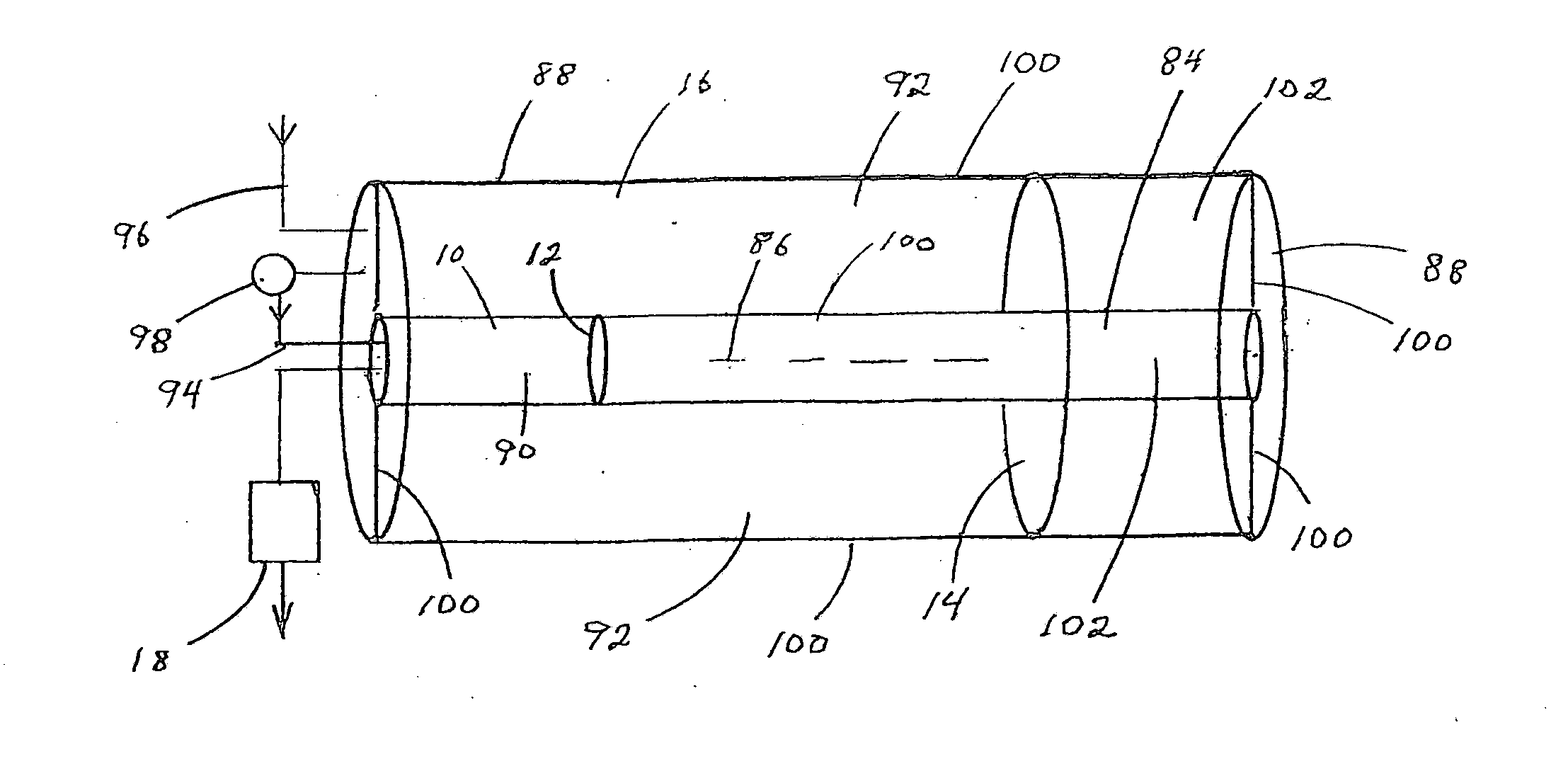
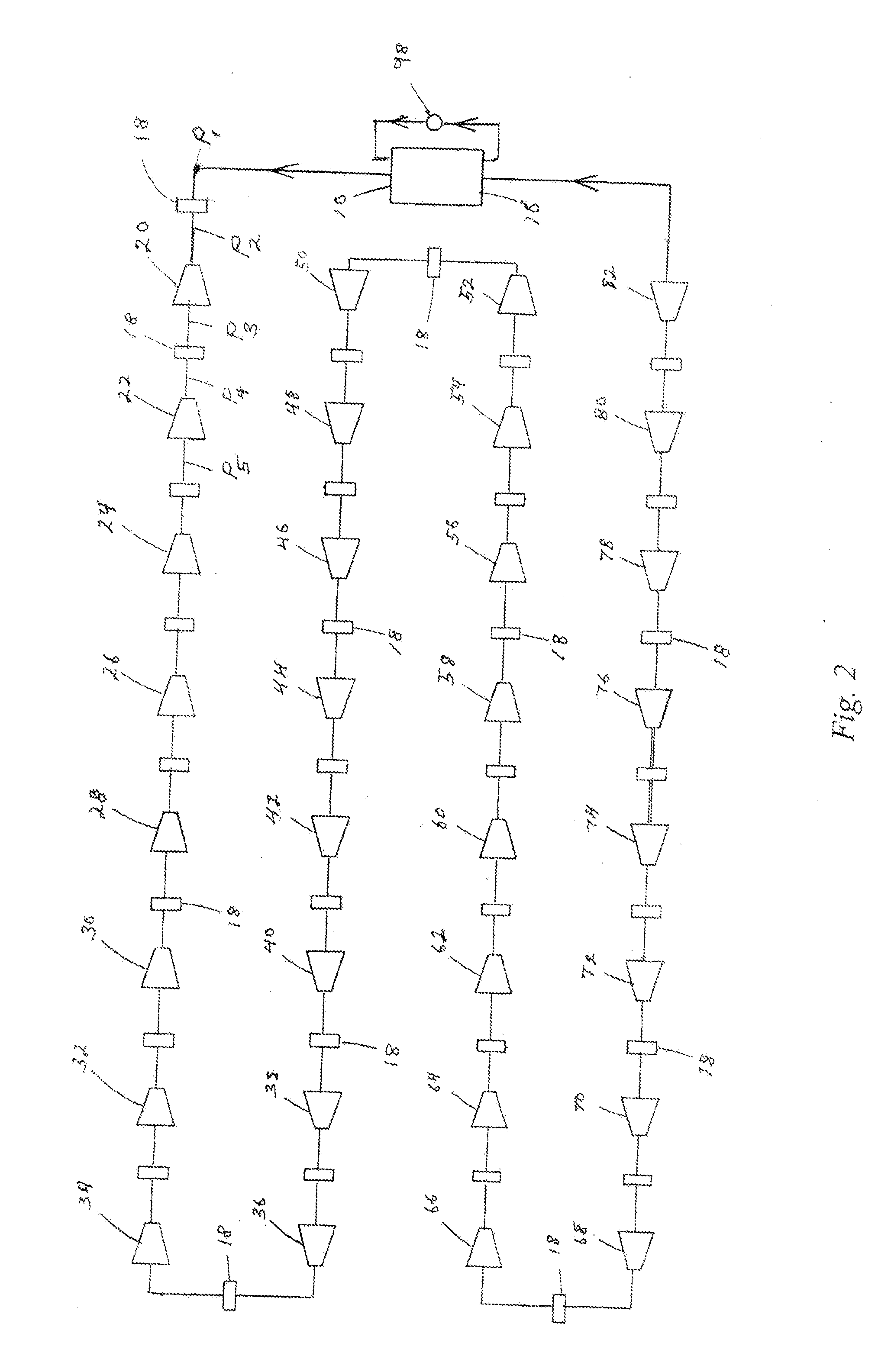
[0022]In the preferred embodiment of the invention, a closed cycle, non-condensing, cryogenic engine is presented using compressed hydrogen gas as its constant-phase working fluid, and the heat energy in the natural environment as its high-temperature heat reservoir. The natural heat energy of the environment is extracted by isothermally compressing the gaseous working fluid at a sub-ambient temperature to 600 Bar by absorbing the heat of compression by evaporating water at sub-ambient temperature and feeding the compressed sub-ambient working fluid into a heat exchanger maintained in thermal contact with large amounts of flowing atmospheric air at natural ambient temperature where it is isobarically heated to ambient temperature TH. The heated compressed gas is withdrawn from the heat exchanger and fed into the first isentropic cryogenic expander of a large plurality of serially connected cryogenic expanders having very low pressure ratios. The first expander expands the very high ...


PUM


Abstract

A closed-cycle cryogenic engine is provided for propelling vehicles or generating electricity at high power densities without consuming any working fluid. The engine comprises a working fluid having a high specific heat that remains in a gaseous phase. The high temperature heat reservoir is the natural environment and the low temperature heat reservoir is created artificially by evaporating water. By isothermally compressing the working fluid at low temperature by absorbing the heat of compression by evaporating water, it is possible to extract a large amount of natural heat energy from the environment and convert a large fraction of it into net output work. Since the latent heat of evaporating water is very high, very little water is consumed which represents the engine's only fuel.

Description

BACKGROUND [0001]For hundreds of years engineers and scientists have recognized that the ambient thermal energy of the natural environment that is heated by the sun contains essentially unlimited amounts of free thermal energy. Unfortunately, all prior attempts to harness this natural heat energy and convert it into mechanical work with high power densities by a closed cycle heat engine utilizing the natural environment as its high temperature heat reservoir have failed. As a result of all of these unsuccessful attempts, thermodynamicists have concluded that such engines are impossible. However, it is important to point out that this negative conclusion is not based on any fundamental physical law of nature but rather on the unsuccessful attempts to construct such engines. Although the “second law of thermodynamics” is usually cited as the basic reason why such engines are believed to be impossible, the second law itself is based on unprovable “postulates” laid down by Kelvin, Claus...

Claims


Application Information

Patent Timeline
IPC IPC(8): F03G7/06F03G6/00F24V50/00
CPCF03G6/003F03G7/06Y02E10/46F03G7/04F03G7/00F24V50/00Y02E60/16F01K15/02F17C1/12F01K25/10F02C1/10F02C1/05F02C6/16F03G7/06112
Inventor MINOVITCH, MICHAEL
Owner MINOVITCH MICHAEL
Why Eureka
Try Eureka