Duct holding structure for battery assembly body

a technology of ducts and battery assemblies, which is applied in the direction of batteries, cell components, electrical devices, etc., can solve the problems of reducing the ease of attachment of the cover member to the case, increasing the size and complexity of the battery assembly body, and prone to deformation, so as to prevent the deformation of the duct more reliably

Active Publication Date: 2015-12-24
YAZAKI CORP +1
View PDF5 Cites 7 Cited by
  • Summary
  • Abstract
  • Description
  • Claims
  • Application Information

AI Technical Summary

Benefits of technology

[0015]The duct holding structure for a battery assembly body

Problems solved by technology

However, in this structure, the cover member is formed over the width of the electrode surfaces of the battery assembly body, resulting in problems that components that are attached to the battery assembly body are increased in

Method used


Image

  • Duct holding structure for battery assembly body
  • Duct holding structure for battery assembly body
  • Duct holding structure for battery assembly body

Examples


Embodiment Construction

[0019]A duct holding structure for a battery assembly body according to an embodiment of the present invention will be hereinafter described with reference to the accompanying drawings. Battery assemblies according to the invention are typically ones applied to power devices that are installed in, for example, electric vehicles that run on the drive power of an electric motor and hybrid vehicles that run on the drive power of an engine and an electric motor and supply power to the electric motor. It goes without saying that battery assemblies according to the invention are not limited to those and can also be applied to power devices etc. of other kinds of movable bodies.

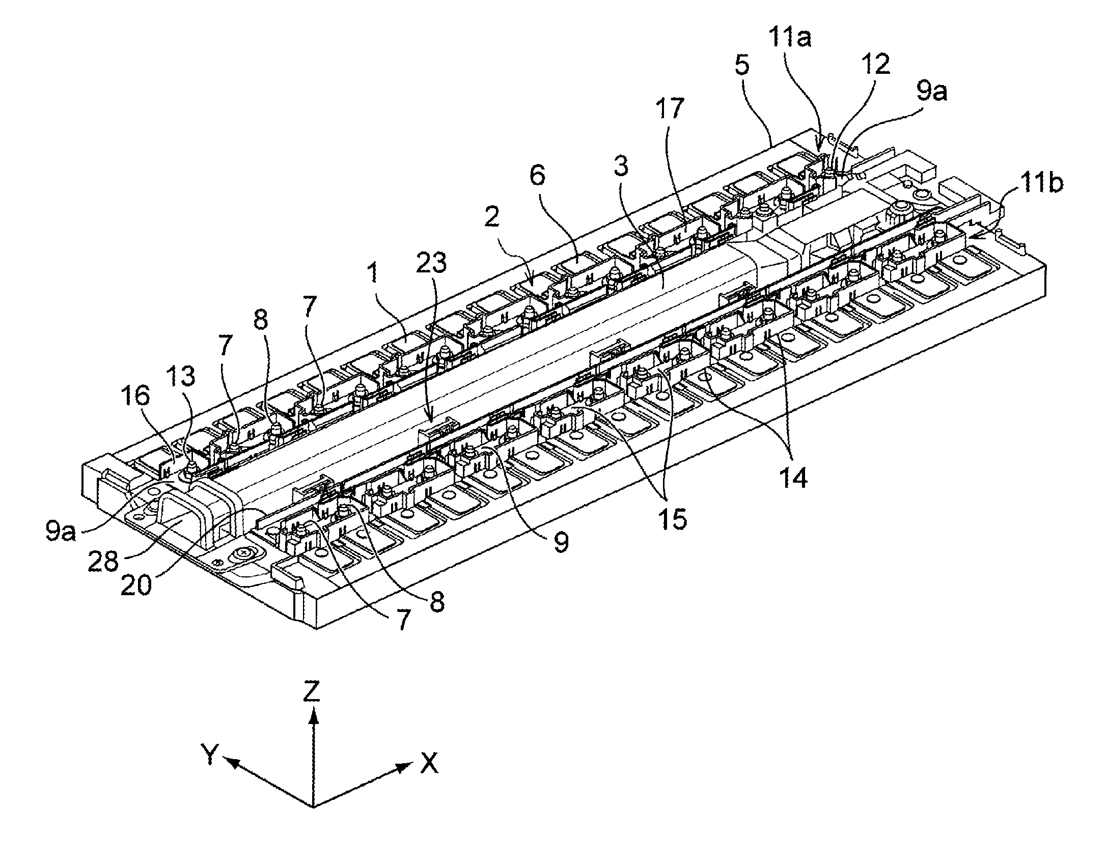
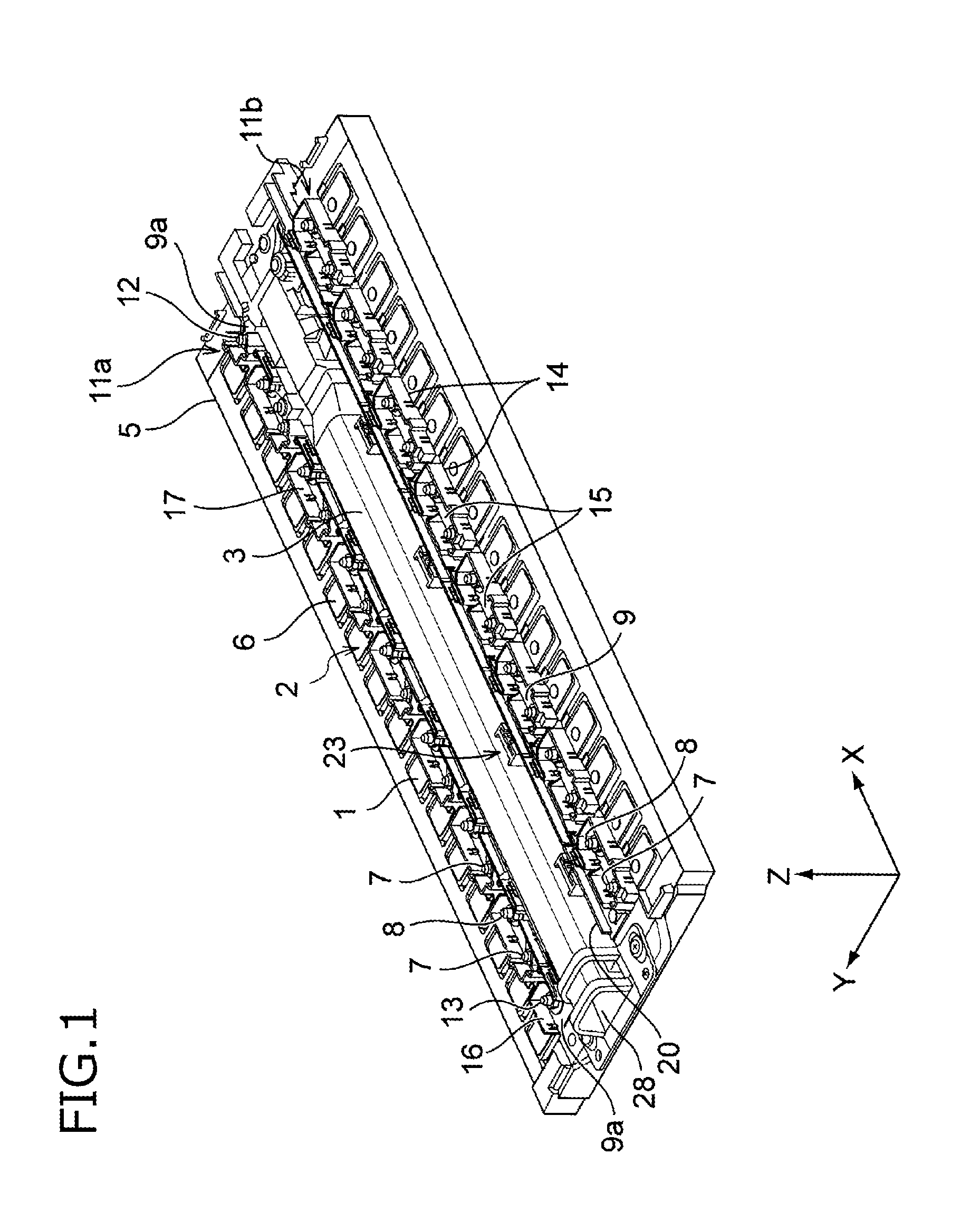
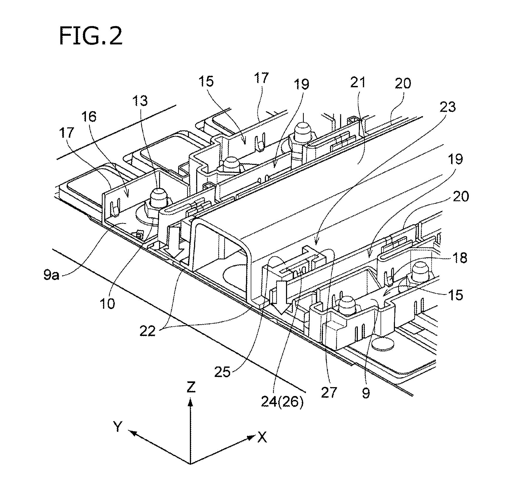
[0020]FIG. 1 is a perspective view showing a configuration in which a duct 3 is held by a battery assembly body 2 which consists of plural batteries 1. In FIG. 1, as for the battery assembly body 2, its surface to which the duct 3 is attached and its vicinity are shown. FIG. 2 is an enlarged perspective view of part...


PUM


Abstract

A duct holding structure includes insulating resin busbar modules (11a, 11b) which are attached to a battery assembly body (2) in which plural batteries (1) are arranged and connected to each other in series, and hold busbars (9) each of which connects electrodes of adjoining ones of the batteries (1); and an insulating resin duct (3) which is attached to the battery assembly body (2) while covering gas vents that are formed through an electrode surface (6) from which the electrodes of the batteries (1) project. The duct (3) and the busbar modules (11a, 11b) are provided with lock mechanisms (23) which lock the busbar modules (11a, 11b) on the duct (3).

Description

TECHNICAL FIELD[0001]The present invention relates to a duct holding structure for a battery assembly body.BACKGROUND ART[0002]The following Patent document 1 discloses a battery assembly body that is configured in such a manner that plural batteries each having a rectangular parallelepiped shape and the positive pole and the negative pole of each adjoining pair of batteries are connected to each other in series by a busbar. Each of the batteries constituting the battery assembly body is formed with a gas vent (hereinafter referred to as a vent where appropriate) for venting gas that is generated inside the battery. For example, this vent is formed by forming an opening through a side wall of the battery and closing it by a thin metal film or the like. With this structure, gas that is generated inside the battery is discharged through the vent breaking the metal film when the pressure inside the battery has become higher than or equal to a prescribed value.[0003]In this type of batt...

Claims


Application Information

Patent Timeline
IPC IPC(8): H01M2/12H01M50/209H01M50/358H01M50/367H01M50/507H01M50/51
CPCH01M2/1061H01M2/1077H01M2220/20H01M2/202H01M2/1264H01M2/1252Y02E60/10H01M50/209H01M50/507H01M50/367H01M50/51H01M50/358H01M50/394
Inventor ICHIKAWA, YOSHIAKIKOIZUMI, KOJITSUCHIYA, TAKENORI
Owner YAZAKI CORP
Why Eureka
Try Eureka