Disconnection indicator of an active component of a device for protecting an electrical installation

a technology for disconnection indicators and electrical installations, applied in emergency protective arrangements for limiting excess voltage/current, installation of lighting conductors, and arrangements responsive to excess voltage, etc., can solve the problems of limited material wear and blockage risk due to this movement, and achieve the effect of no friction and limited siz

Active Publication Date: 2015-12-24
ABB FRANCE SAS
View PDF4 Cites 3 Cited by
  • Summary
  • Abstract
  • Description
  • Claims
  • Application Information

AI Technical Summary

Benefits of technology

[0016]Thanks to the dispositions according to the invention, the indicator of the connected or disconnected state of the active component is integrated to the disconnection system and thus has a limited size. In addition, no friction is caused by the passage of the moveable part of the connection element, and hence of the disconnection indicator, from the contact position to the closed position. Thus, the wear of the materials as well as the risks of blocking due to this movement are limited. Finally, this type of indicator does not cause any additional energy consumption.

Problems solved by technology

Thus, the wear of the materials as well as the risks of blocking due to this movement are limited.

Method used


Image

  • Disconnection indicator of an active component of a device for protecting an electrical installation
  • Disconnection indicator of an active component of a device for protecting an electrical installation
  • Disconnection indicator of an active component of a device for protecting an electrical installation

Examples


Embodiment Construction

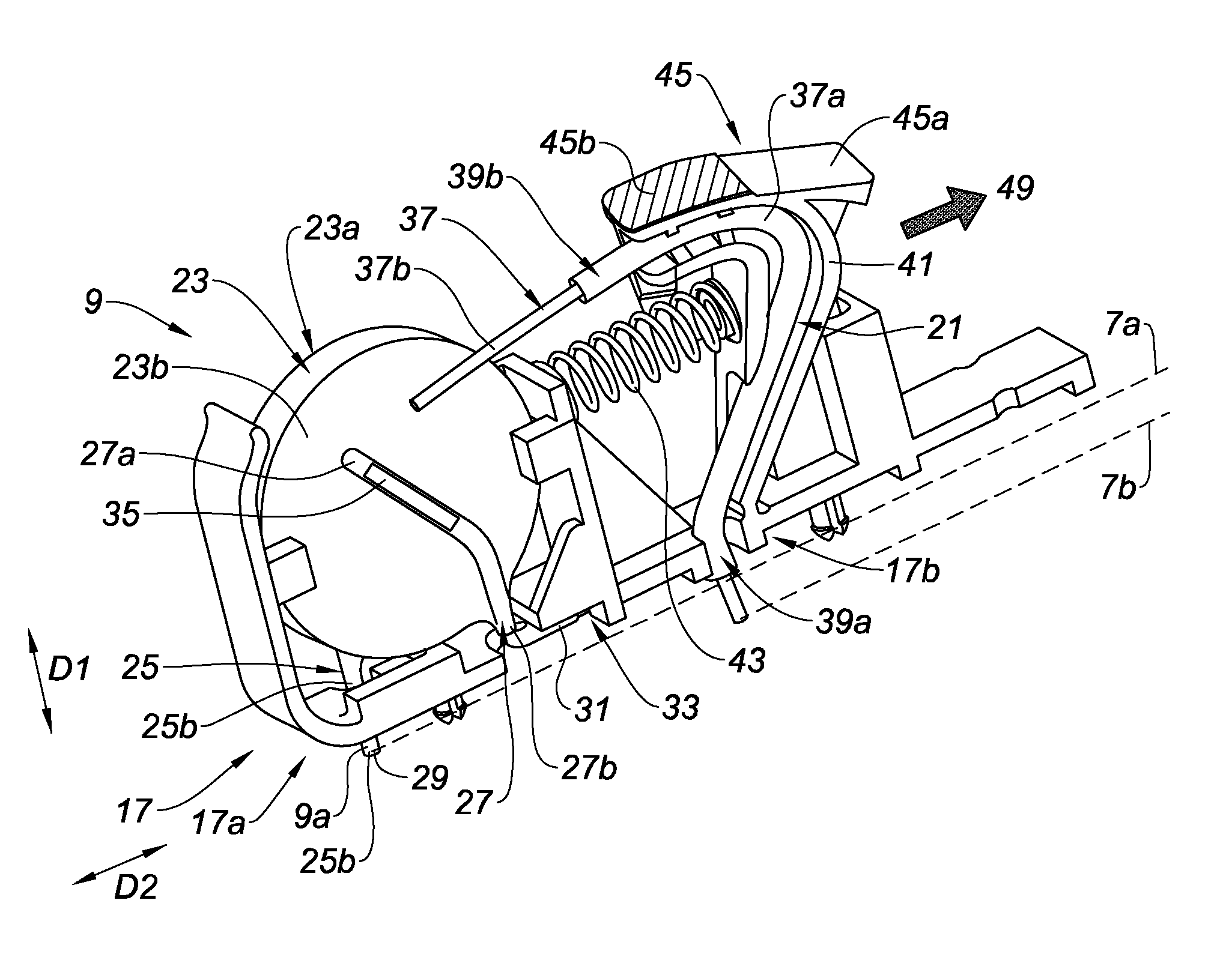
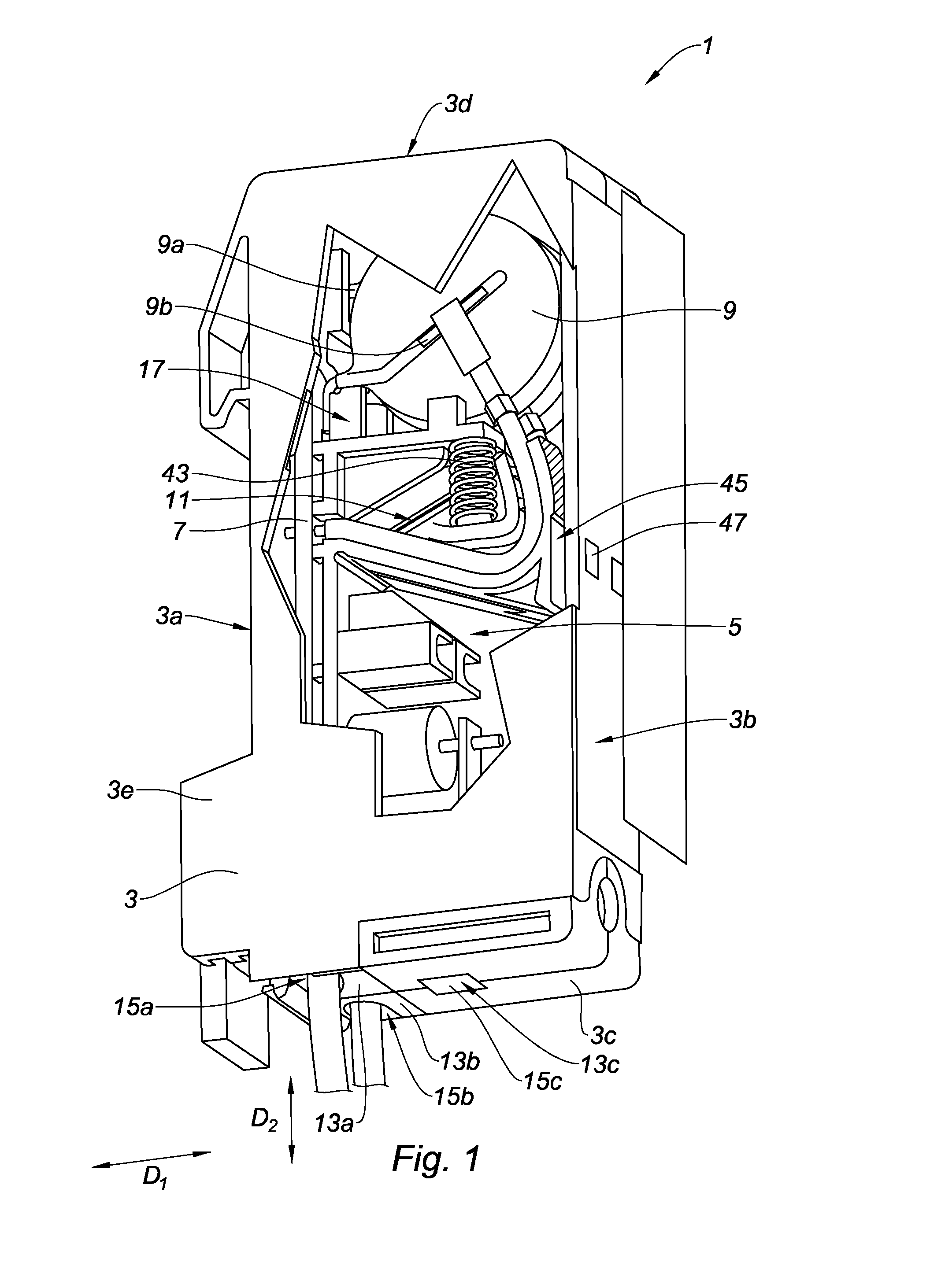
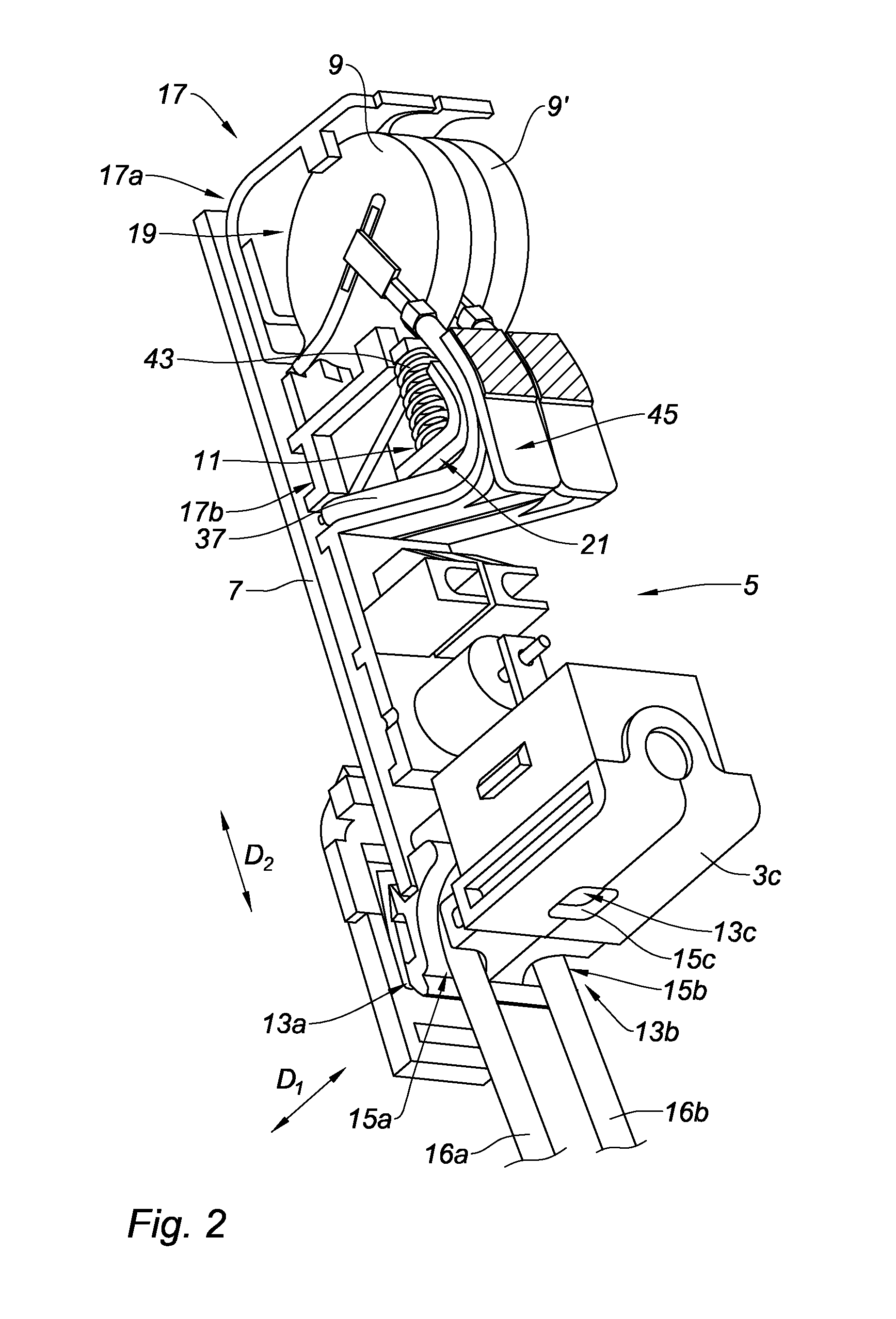
[0087]FIG. 1 represents a device 1 for protecting an electrical installation intended to be added onto a support (not represented), for example a DIN type rail, within an electrical box along a substantially vertical direction. The protective device 1 comprises an electrically insulating body 3, substantially parallelepiped. The insulating body 3 comprises a rear face 3a intended to be fixed onto the support. The insulating body 3 further comprises a front face 3b opposite the rear face 3a, visually accessible when the device is added onto the support. The front 3b and rear 3a faces define an internal housing 5 along an extension direction D1. The insulating body comprises a face 3c, destined to be the lower face of the insulating body 3 when the protective device 1 is added onto the support, that is to say, during operation. A face 3d, solid and opposite the face 3c is intended to be the upper face of the insulating body 3 when the protective device 1 is added onto the support. The...


PUM


Abstract

A device for protecting an electrical installation including an insulating body electrically defining an internal housing, the protective device including, within the internal housing: an active component of a device for protecting an electrical installation; a disconnection system for disconnecting the active component moveable between a contact position corresponding to a connected state of the active component and an open position corresponding to a disconnected state of the active component; a disconnection indicator, where the disconnection indicator is secured in movement to the disconnection system and the disconnection indicator and the insulating body are arranged to have a first configuration, which corresponds to the contact position, and a second configuration, which corresponds to the open position, the relative positioning of the disconnection indicator with respect to the insulating body in the first configuration being visually distinct from the outside of the insulating body from the relative positioning of the disconnection indicator with respect to the insulating body in the second configuration.

Description

CROSS REFERENCE TO RELATED APPLICATION[0001]This application is related to and claims the benefit of European Patent Application Number 14 / 55681 filed on 20 Jun. 2014, the contents of which are herein incorporated by reference in their entirety.TECHNICAL FIELD[0002]The present invention relates to a device for protecting an electrical installation comprising a system for disconnecting an active component of the device with visual indicator.BACKGROUND[0003]A varistor is an active component of a device for protecting an electrical installation, such as a lightning arrester. Current varistors, or variable resistors comprise a ceramic block for example composed of zinc oxide assembled by sintering and have a non-linear current / voltage characteristic: beyond a certain voltage threshold, the varistor impedance drops to allow the discharge of current following a voltage surge. When the voltage returns to its normal level, the varistor impedance assumes its value at the standby state.[0004]...

Claims


Application Information

Patent Timeline
Patent Type & Authority Applications(United States)
IPC IPC(8): H02H3/04H02H3/22
CPCH02H3/04H02H3/22H01H2037/762H01H37/08H01H37/761H01C7/126H02G13/00
Inventor GAUTIER, BORISBRESCON, STEPHANE
Owner ABB FRANCE SAS
Why Eureka
Try Eureka