Hyperthermia for diagnostic imaging

a diagnostic imaging and hyperthermia technology, applied in the field of magnetic resonance imaging, can solve the problems of difficult measurement of ineffective treatment, cell death due to chemotherapy or tissue necrosis due to heating, etc., and achieve the effect of reducing local hypoxia, improving diagnostic image representation, and reducing local hypoxia

Inactive Publication Date: 2015-12-31
KONINKLJIJKE PHILIPS NV
View PDF21 Cites 2 Cited by
  • Summary
  • Abstract
  • Description
  • Claims
  • Application Information

AI Technical Summary

Benefits of technology

[0033]According to a preferred embodiment the method for providing a diagnostic image representation comprises applying a contrast agent to the subject of interest. The contrast agent can be used to improve the diagnostic image representation in respect to changes of the metabolism of the subject of interest. Contrast agents can be sensitive to heat shock proteins, oxygen concentration, radiation damage or others.
[0034]According to a preferred embodiment of the method for providing a diagnostic image representation the step of providing a diagnostic image representation of the portion of the subject of interest with the correlated image representations comprises identifying hypoxic areas within the portion of the subject of interest. Cancerous cells frequently show a reduced local hypoxia. By comparing the difference between the first and second temperature signals of the target zone, the amount of hypoxia can be estimated, and the amount of treatment damage to the cells can be estimated from the temporally altered response due to the thermal stress. The hypoxia information can be fed back to dose calculations even before the treatment starts, to boost the dose on hypoxic volumes. The damage estimation can be used to optimize the amount of dose to minimize damage to healthy tissue while ensuring the effectiveness of treatment on the target zone during the irradiation or a single fraction. For example, with blood oxygen level dependent (BOLD) image representations, hypoxic tissue does not show a similar change due to different temperatures as normal tissue.
[0035]According to a preferred embodiment of the method for treatment of a subject of interest the step of applying a treatment dose for destroying cells within the target zone of the subject of interest comprises locally heating the target zone. In addition to improving location and doses of the treatment, the hyperthermia can be used to enhance the outcome of the treatment, i.e., the treatment effectiveness can be improved by hyperthermia. This is partly due to increased metabolism, altered blood-flow, and reduced local hypoxia often present in cancerous tissue. Due to the locally applied heat, cells outside the target zone are not subject to an increased destruction.

Problems solved by technology

Diagnostic imaging like magnetic resonance imaging (MRI) is becoming a more important issue in the area of therapy.
Nevertheless, the effectiveness of the treatment is not known during the irradiation treatment.
Similarly, the cell death due to chemotherapy or tissue necrosis due to heating is difficult to measure.

Method used


Image

  • Hyperthermia for diagnostic imaging
  • Hyperthermia for diagnostic imaging
  • Hyperthermia for diagnostic imaging

Examples


Embodiment Construction

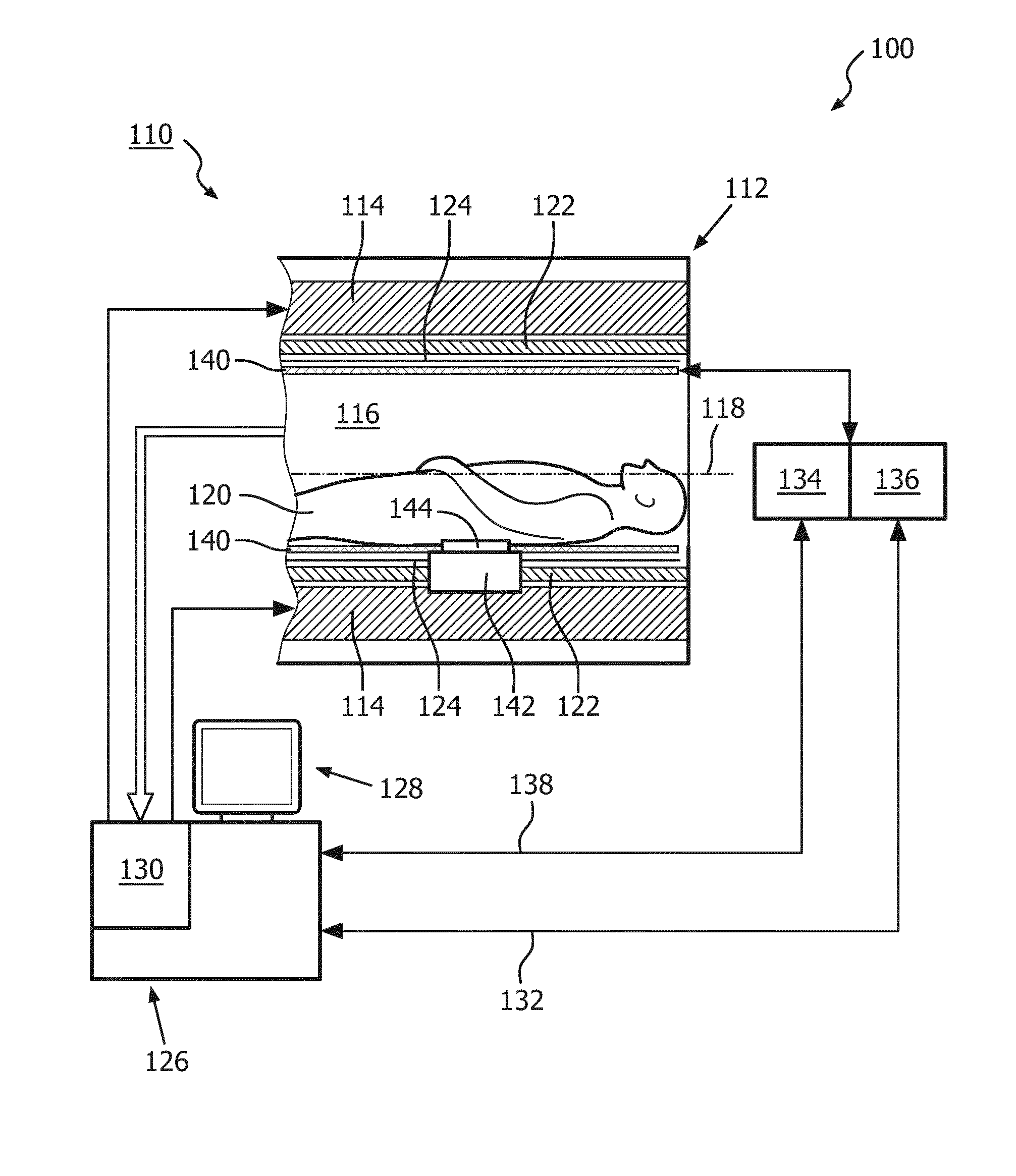
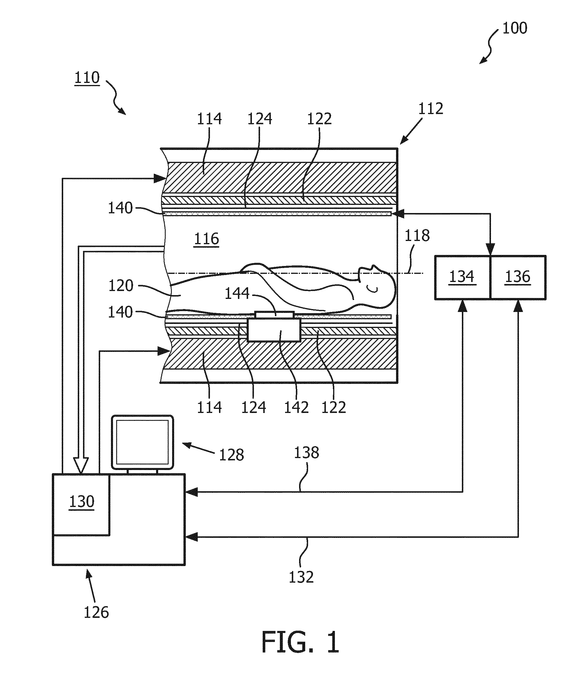
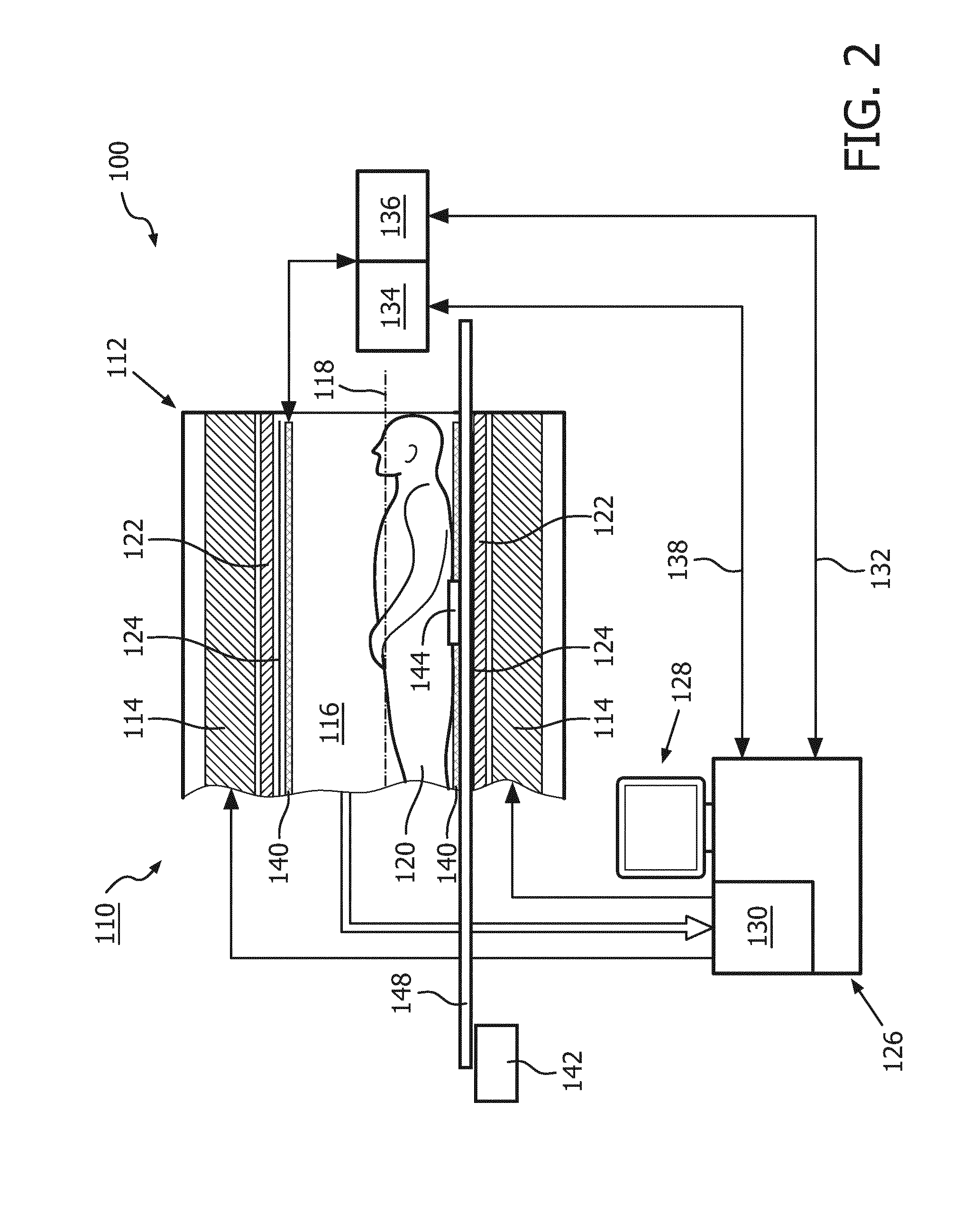
[0041]FIG. 1 shows a schematic illustration of an embodiment of a diagnostic imaging system 100 comprising a magnetic resonance (MR) imaging system 110 and a hyperthermia device 111.

[0042]The MR imaging system 110 comprises an MR scanner 112 and includes a main magnet 114 provided for generating a static magnetic field. The main magnet 114 has a central bore that provides an examination space 116 around a center axis 118 for a subject of interest 120, usually a patient, to be positioned within. In this embodiment, the central bore and therefore the static magnetic field of the main magnet 114 has a horizontal orientation in accordance with the center axis 118. In an alternative embodiment, the orientation of the main magnet 114 can be different. Further, the MR imaging system 110 comprises a magnetic gradient coil system 122 provided for generating gradient magnetic fields superimposed to the static magnetic field. The magnetic gradient coil system 122 is concentrically arranged wit...


PUM


Abstract

The present invention provides a diagnostic imaging system (100), comprising a magnetic resonance (MR) imaging system (110) for providing an image representation of at least a portion of a subject of interest (120) positioned in an examination space (116), a hyperthermia device (111) for locally heating a target zone within the portion of the subject of interest (120), and a control unit (126) for controlling the MR imaging system (110) and the hyperthermia device (111), wherein the diagnostic imaging system (100) is adapted to provide a diagnostic image representation of the portion of the subject of interest (120) by correlating image representations obtained at different temperatures of the target zone, wherein the diagnostic image representation comprises information on temperature dependent changes of the metabolism of the subject of interest (120). The invention further provides a treatment system comprising the above diagnostic imaging system (100), a treatment module (146) for applying a treatment to the subject of interest (120) for destroying cells within the target zone, and a control module (126) for controlling the treatment module (146) for applying the treatment based on diagnostic image representations obtained by the diagnostic imaging system (100). Accordingly, changes of the metabolism of the subject of interest can be evaluated to direct a treatment to such areas, where the cells have not yet been destroyed as desired. By comparing the difference of the above measurements between the first and the second temperature, the efficiency of the treatment can be evaluated and the further treatment can be adapted based on the metabolism changes.

Description

FIELD OF THE INVENTION[0001]The invention relates to the field of diagnostic imaging, in particular magnetic resonance imaging, and treatments for destroying cells within a subject of interest.BACKGROUND OF THE INVENTION[0002]Diagnostic imaging like magnetic resonance imaging (MRI) is becoming a more important issue in the area of therapy. In particular, diagnostic imaging is used in the area of cancer treatments to plan an efficient treatment of cancerous tissues in an area of interest of the subject of interest, as described e.g. in WO 02 / 082995 A1. As described therein, a magnetic resonance (MR) apparatus is used to plan a treatment regimen using a linear accelerator (linac). The features of slice width selection and depth selection are used to better ascertain where a medial malignancy is within a subject of interest, which is an animate being, e.g. a human being or an animal. A conversion algorithm translates the linac input into an imaging region for a magnetic resonance seque...

Claims


Application Information

Patent Timeline
Patent Type & Authority Applications(United States)
IPC IPC(8): A61B5/00A61N7/02A61B5/01A61N1/40G06T7/00A61B5/055
CPCA61B18/14A61B2018/00738A61N2007/0082A61N2005/1055A61N7/02A61B5/015A61B5/055G01R33/4814A61N5/1039G06T7/0012A61N1/403A61B5/743A61B5/4836G06T2207/30004G06T2207/10096G06T2207/30196A61B2090/374A61B2018/00791A61B5/0036
Inventor VAHALA, ERKKI TAPANI
Owner KONINKLJIJKE PHILIPS NV
Why Eureka
Try Eureka