

Hydraulic system for construction machinery
a technology of construction machinery and hydraulic system, which is applied in the direction of fluid couplings, servomotors, couplings, etc., can solve the problems of irregularity in the operation of the front structure, abnormal control of the return fluid, etc., and achieve the effect of smooth descen
- Summary
- Abstract
- Description
- Claims
- Application Information
AI Technical Summary
Benefits of technology
Problems solved by technology
Method used
Image

Examples
first embodiment
1. Construction Machinery
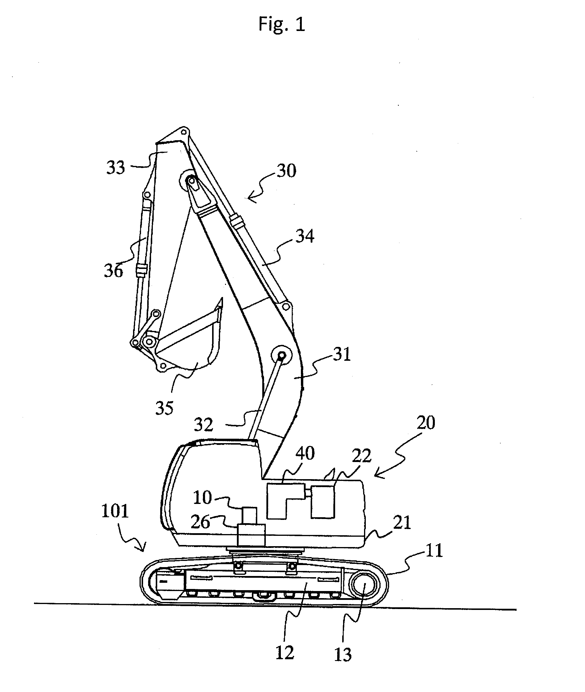
[0016]FIG. 1 is a schematic diagram showing a hydraulic excavator as an example of the target of application of the hydraulic system according to the present invention.
[0017]The hydraulic excavator shown in FIG. 1 comprises a track structure 101, a swing structure (main body) 20, an excavation mechanism (front structure) 30, and a hydraulic system 40.
[0018]The track structure 101 includes a pair of (left and right) crawlers 11 (only one side is shown in FIG. 1), a crawler frame 12 as the frame for the crawlers 11, left and right travel hydraulic motors 13 provided respectively for the left and right crawlers 11, deceleration mechanisms provided respectively for the left and right travel hydraulic motors 13, and so forth.
[0019]The swing structure 20 includes a swing frame 21, an engine (prime mover) 22 mounted on the swing frame 21, a swing hydraulic motor 10 for swinging (rotating) the swing structure 20 with respect to the track structure 101, a deceleratio...
second embodiment
1. Configuration
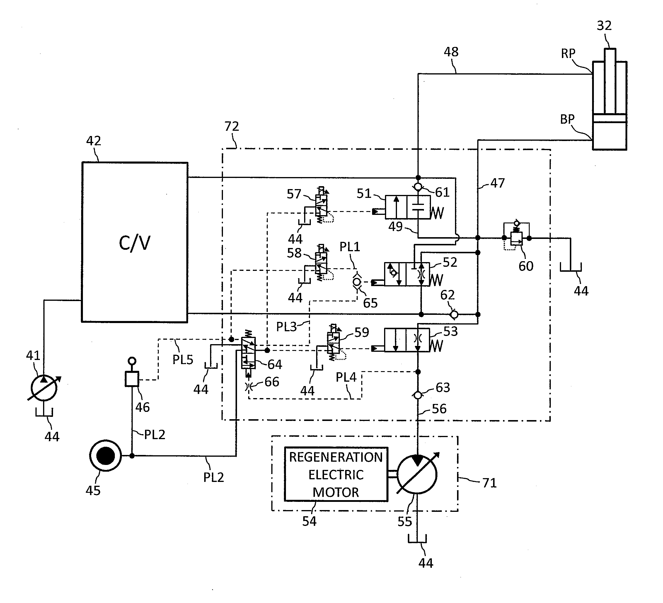
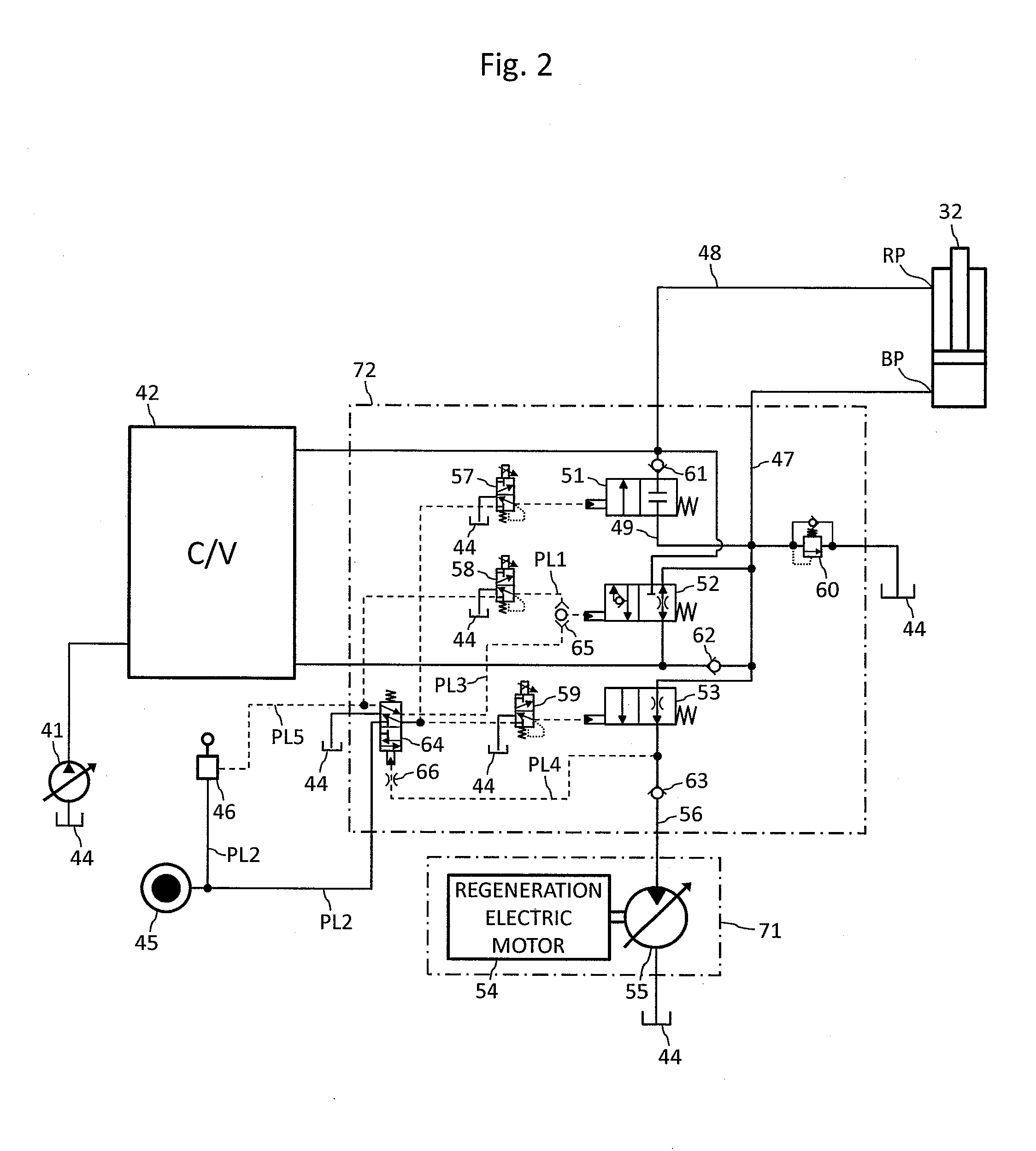
[0049]FIG. 3 is a hydraulic circuit diagram of a hydraulic system in accordance with a second embodiment of the present invention including an energy regeneration circuit. Elements in FIG. 3 equivalent to those in FIG. 2 (first embodiment) are assigned the same reference characters as in FIG. 2 and repeated explanation thereof is omitted for brevity.
[0050]This embodiment differs from the first embodiment only in the configuration of the malfunction prevention device. In this embodiment, a rapid deceleration prevention valve 68 and a shuttle valve 67 are provided as the malfunction prevention device as shown in FIG. 3. The quick acceleration prevention valve 64, the fixed restrictor 66, the shuttle valve 65 and the pilot line PL4 which have been explained referring to FIG. 2 are left out.
[0051]One input port of the shuttle valve 67 is connected to the secondary pressure port of the solenoid valve for flow control valve 58 via the pilot line PL1, while the...
third embodiment
[0057]FIG. 4 is a hydraulic circuit diagram of a hydraulic system in accordance with a third embodiment of the present invention including an energy regeneration circuit. Elements in FIG. 4 equivalent to those in FIG. 2 (first embodiment) are assigned the same reference characters as in FIG. 2 and repeated explanation thereof is omitted for brevity.
1. Configuration
[0058]This embodiment differs from the first embodiment in the configuration of the malfunction prevention device. As shown in FIG. 4, a bypass shut-off valve 70 is employed in this embodiment as a valve serving also as the malfunction prevention device. The quick acceleration prevention valve 64, the fixed restrictor 66, the shuttle valve 65 and the pilot line PL4 which have been explained referring to FIG. 2 are left out.
[0059]The bypass shut-off valve 70, as a selector valve having an open position and a drain position, is arranged in a pilot line PL9 connecting the solenoid valve for bypass valve 57 to the bypass valve...
PUM
 Abstract
Description
Claims
Application Information