Supercharge Your Innovation With Domain-Expert AI Agents!

External-electrode discharge lamp with no light leakage from external electrode portion

a discharge lamp and electrode technology, applied in the direction of soldering apparatus, instruments, manufacturing tools, etc., can solve the problems of increased thickness of display panels, increased manufacturing costs, and increased power supply for turning on lamps

Inactive Publication Date: 2009-10-20
NEC CORP
View PDF30 Cites 0 Cited by
  • Summary
  • Abstract
  • Description
  • Claims
  • Application Information

AI Technical Summary

Benefits of technology

The present invention provides an external-electrode discharge lamp that can prevent light leakage from the external electrode and maintain good contact between the external electrode and the outer casing or glass bulb over time. The external electrode is brazed or bonded to the outer casing or glass bulb using a brazing material or an inorganic adhesive, which prevents irregularities in the contact between the external electrode and the outer casing or glass bulb. The external electrode is made of a light-permeable, electrically insulating material or a light-impermeable, electrically conductive layer that is fixed to the outer casing or glass bulb. The external-electrode discharge lamp has a closed hollow space defined by the outer casing or glass bulb, and the light is blocked from leaking by the brazing material or the inorganic adhesive. The external electrode can be fixed to the outer casing or glass bulb using a brazing material or an inorganic adhesive. The external-electrode discharge lamp has an external electrode that extends fully circumferentially on the outer surface of the outer casing or glass bulb, preventing light leakage and improving the contact between the external electrode and the outer casing or glass bulb.

Problems solved by technology

If the number of lamps in the edge-light backlight is increased, then many lamps are stacked, resulting in an increase in the thickness of the display panel.
As a result, a power supply for turning on the lamps becomes larger in size and more expensive to manufacture.
Therefore, a large discharge current necessarily flows in the external-electrode discharge lamps, and a large amount of heat is inevitably produced thereby.
Since the electrically conductive thin film used as the external electrodes have a limited heat radiation capability, a vicious cycle occurs which is successively made up of an increase in the temperature of the glass bulb, a reduction in the insulation of the glass bulb, an increase in the current, an increase in the amount of generated heat, and a further increase in the temperature of the glass bulb.
As a consequence, holes tend to be formed in the glass bulb beneath the external electrodes.
An electrically conductive thin film for use as an external electrode is likely to be fabricated according to a complex production process and hence at a high cost.
However, simply fitting the C-shaped metal ring over the glass bulb tends to cause irregular contact between the glass bulb and the ring.
As a consequence, the glass bulb and the external electrode are not held in full effective surface-to-surface contact with each other, but held in contact with each other through a small effective area, resulting in a reduced amount of electric power applied to the discharge lamp.
In addition, a discharge current is liable to concentrate in the area where the contact resistance is smaller.
As a consequence, holes tend to be formed in the glass bulb beneath the external electrode.
One problem with the C-shaped external electrode is that light tends to leak from the gap in the C shape of the external electrode.
The light leakage is fatal if the discharge lamp is used as the light source of a backlight for liquid crystal display devices because light is emitted from the edge of the liquid crystal display panel which should not be light-emitting.
In addition, the radiation emitted from the gap of the external electrode, which is radiated not through the fluorescent layer of the lamp, contains many ultraviolet rays that are liable to deteriorate plastic members such as light guide plates.
Another problem is that the area of the external electrode is reduced because of the gap in the C shape thereof.
The structure in which the C-shaped external electrode is mounted on the glass bulb while pressing the glass bulb under its spring resiliency tends to introduce irregularities into the contact between the glass bulb and the external electrode.
As described above, the irregular contact between the glass bulb and the external electrode is liable to form holes in the portion of the glass bulb beneath the external electrode.
Consequently, this structure does not fully solve the problem of the irregular contact.
If the structure in which the C-shaped external electrode is fixed to the glass bulb by the electrically conductive adhesive is used for a long period of time, close contact will be lost between the external electrode and the glass bulb.
If the electrically conductive adhesive is used to secure the external electrode to the glass bulb, the binder resin is deteriorated with time by ultraviolet rays radiated through the glass bulb.
Consequently, the contact between the external electrode and the glass bulb is impaired with time.
However, such organic resins have low bonding strength and do no provide sufficiently reliable contact between the external electrode and the glass bulb.

Method used


Image

  • External-electrode discharge lamp with no light leakage from external electrode portion
  • External-electrode discharge lamp with no light leakage from external electrode portion
  • External-electrode discharge lamp with no light leakage from external electrode portion

Examples


1st embodiment

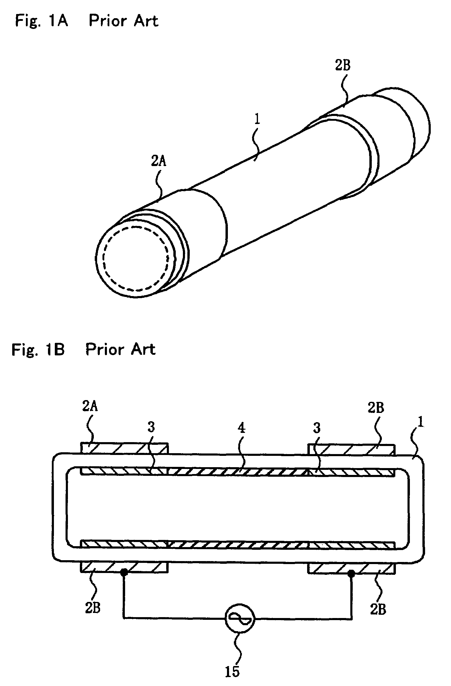
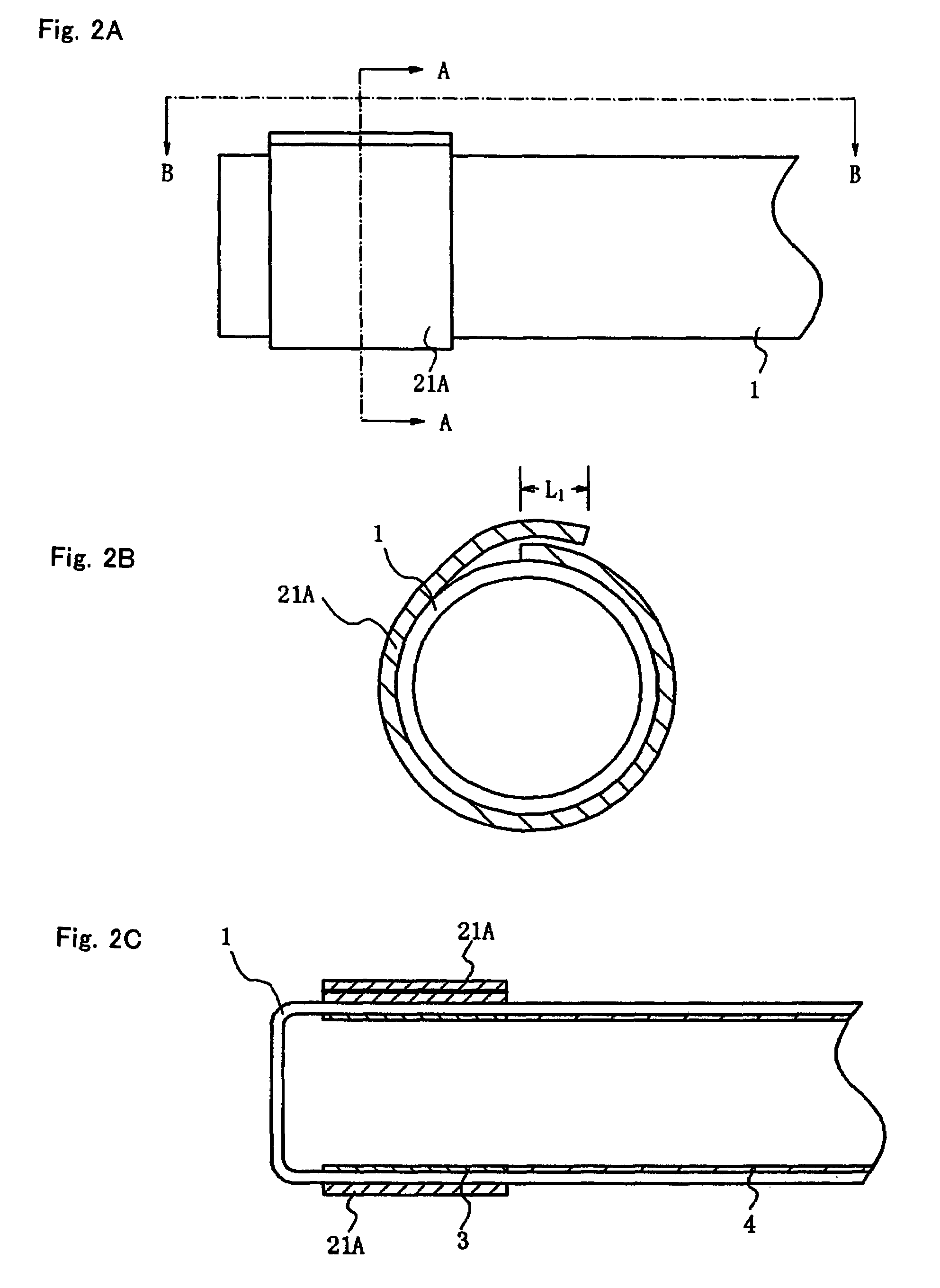
[0060]FIG. 2A shows in side elevation an external-electrode discharge lamp according to a first embodiment of the present invention. FIG. 2B is a transverse cross-sectional view taken along line A-A of FIG. 2A, and FIG. 2C is a longitudinal cross-sectional view taken along line B-B of FIG. 2A. In FIG. 2A, only a portion of the external-electrode discharge lamp which includes one external electrode 21A on one end thereof is illustrated. However, the external-electrode discharge lamp also has another external electrode, which is identical to external electrode 21A, on the other end thereof, as with the case of conventional one shown in FIGS. 1A and 1B. In FIG. 2B, internal structural details of the external-electrode discharge lamp are omitted from illustration.

[0061]The external-electrode discharge lamp according to the first embodiment is a mercury fluorescent lamp that comprises a gas containing mercury vapor as a discharge medium and emits light with the help of a fluorescent mate...

2nd embodiment

[0068]FIG. 3A shows in transverse cross section an external-electrode discharge lamp according to a second embodiment of the present invention. FIG. 3B is a longitudinal cross-sectional view of the external-electrode discharge lamp shown in FIG. 3A. In FIG. 3A, protective layers 3 on the inner surface of glass bulb 1 are omitted from illustration.

[0069]The external-electrode discharge lamp according to the second embodiment is similar to the external-electrode discharge lamp according to the first embodiment in that it has ring-shaped external electrodes 22A with overlapping ends, but differs therefrom in that solder layer 5 is interposed between each external electrode 22A and glass bulb 1.

[0070]As described above, if a C-shaped external electrode is simply fitted over a glass bulb or a metal foil is used as a base for a C-shaped external electrode, as with the conventional structures, then since the external electrode is held only in mechanical contact with the glass bulb or the m...

3rd embodiment

[0090]FIG. 5A shows in transverse cross section an external-electrode discharge lamp according to a third embodiment of the present invention. FIG. 5B is a longitudinal cross-sectional view of the external-electrode discharge lamp shown in FIG. 5A. In FIG. 5A, protective layers 3 on the inner surface of glass bulb 1 are omitted from illustration.

[0091]The external-electrode discharge lamp according to the third embodiment is similar to the external-electrode discharge lamps according to the first and second embodiments in that it has ring-shaped external electrodes 23A with overlapping ends, but differs therefrom in that uninterrupted metal layer 11 extending circumferentially on and around glass bulb 1 and adhesive layer 12 extending on and around metal layer 11 are interposed between each external electrode 23A and glass bulb 1, external electrode 23A being fixedly bonded to glass bulb 1.

[0092]According to the third embodiment, external electrode 23A is bonded to glass bulb 1 by a...


PUM

PropertyMeasurementUnit
pressureaaaaaaaaaa
pressureaaaaaaaaaa
voltageaaaaaaaaaa

Abstract

An external-electrode discharge lamp has a light-permeable, electrically insulative outer casing having a closed hollow space defined therein. A discharge medium is sealed in the outer casing. An external electrode is disposed on an outer surface of the outer casing for causing a dielectric barrier discharge in the discharge medium. The external electrode comprises a plate of an electrically conductive material and is brazed to the outer surface of the outer casing by a brazing material disposed fully circumferentially on the outer surface of the outer casing.

Description

BACKGROUND OF THE INVENTION[0001]1. Field of the Invention[0002]The present invention relates to an external-electrode discharge lamp, and more particularly to an external-electrode discharge lamp for use as the light source of a backlight for a liquid crystal display device having a relatively large screen size and a method of manufacturing such an external-electrode discharge lamp.[0003]2. Description of the Related Art[0004]Discharge lamps are used as the light source of backlights for liquid crystal display devices in one of their applications. A backlight serves to illuminate a liquid crystal display panel from its back. From the standpoint of the layout of a discharge lamp as a light source, backlights are generally classified into a so-called edge-light type and a so-called direct type. The edge-light backlight design includes a discharge lamp as a light source disposed outwardly of an edge of the liquid crystal display panel. In the edge-light backlight design, light emitted...

Claims


Application Information

Patent Timeline
Patent Type & Authority Patents(United States)
IPC IPC(8): H01J65/00H01J61/54B23K35/26G02F1/13357H01J9/14H01J65/04
CPCB23K35/262H01J65/046H01J9/14C22C13/02H01J2893/0002
Inventor MINAMOTO, MAKIFUJIOKA, SEIICHIRO
Owner NEC CORP
Features
  • R&D
  • Intellectual Property
  • Life Sciences
  • Materials
  • Tech Scout
  • Unparalleled Data Quality
  • Higher Quality Content
  • 60% Fewer Hallucinations
Learn More