Drive plate and method for manufacturing the same

Inactive Publication Date: 2015-12-31
AISIN AW CO LTD
View PDF9 Cites 1 Cited by
  • Summary
  • Abstract
  • Description
  • Claims
  • Application Information

AI Technical Summary

Benefits of technology

The technical effect of this patent is to improve the sound quality and sound pressure of gear noise in a drive plate integrally molded by press working. The problem is that the lowering of the gear meshing ratio due to the molding accuracy of the teeth on the rim section can lead to degraded sound quality and sound pressure. To solve this problem, the patent proposes a design that prevents the meshing ratio on the free end side of the rim section from lowing and ensures that the teeth of the rim section well mesh with the teeth of the gear of the motor on the base end side to suppress the degradation of sound quality and gear noise caused by imperfect meshing. This design also improves the sound quality and sound pressure of gear noise during cranking. The patent also describes various methods of deforming the plate section and rim section to accurately couple the plate section to the power transmitting subject and suppress the deformation of the coupling portion with the power transmitting subject. Overall, the patent provides a solution to improve the sound quality and sound pressure of gear noise in a drive plate integrally molded by press working.

Problems solved by technology

However, when the drive plate integrally molded by press working, as described above, is used, the sound quality and the sound pressure of gear noise generated when cranking the engine are not preferable to hear compared to the case in which the drive plate including the plate and the ring gear formed as separate bodies is used.

Method used


Image

  • Drive plate and method for manufacturing the same
  • Drive plate and method for manufacturing the same
  • Drive plate and method for manufacturing the same

Examples


Embodiment Construction

[0025]A preferred embodiment will be described below with reference to the drawings.

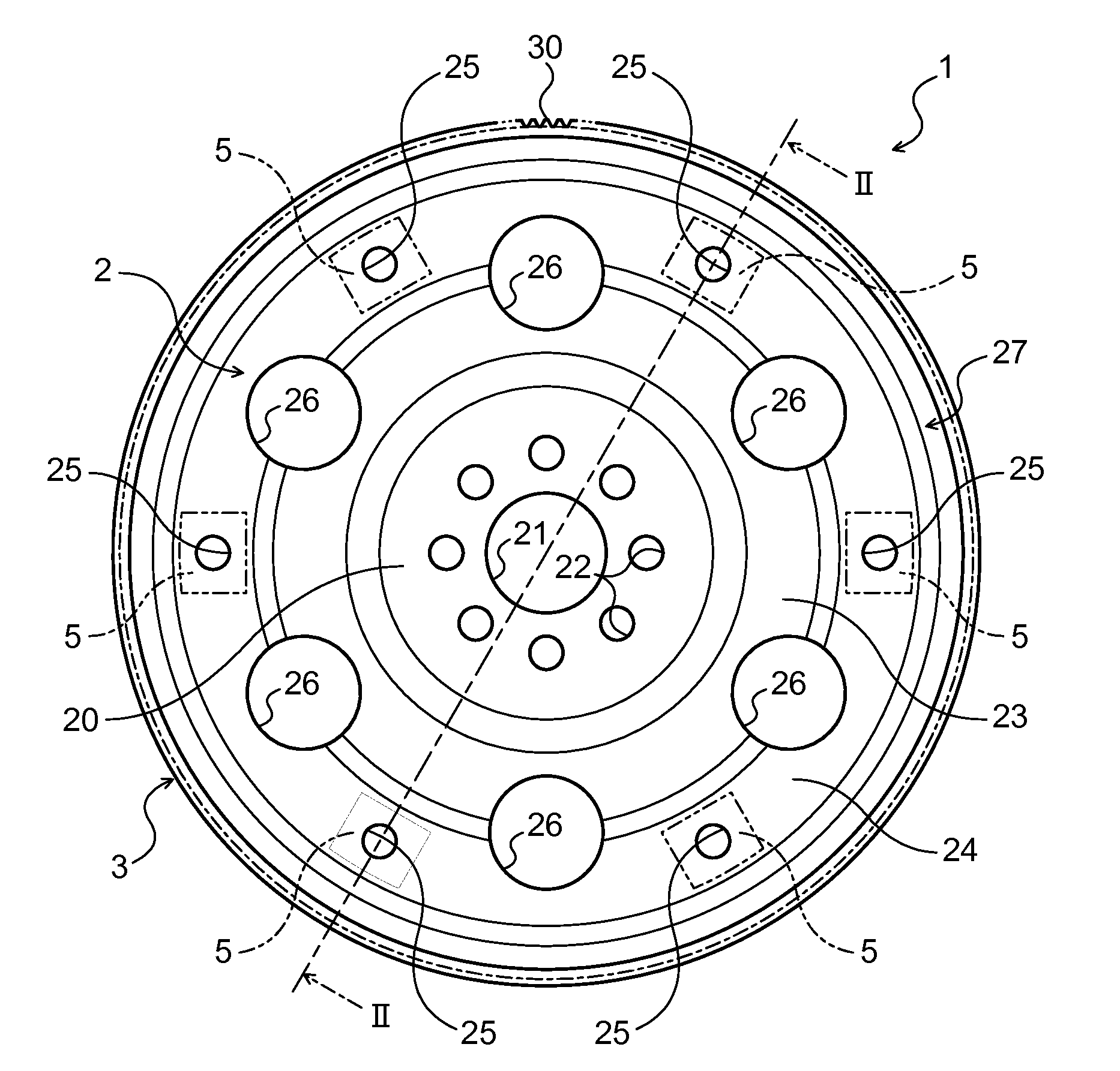
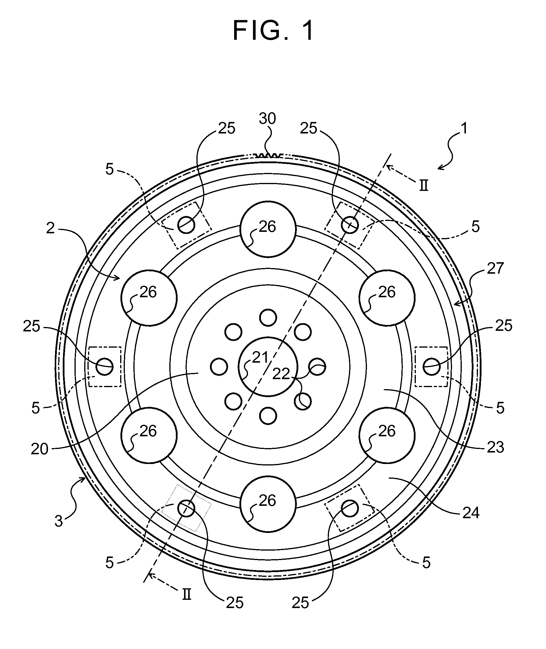
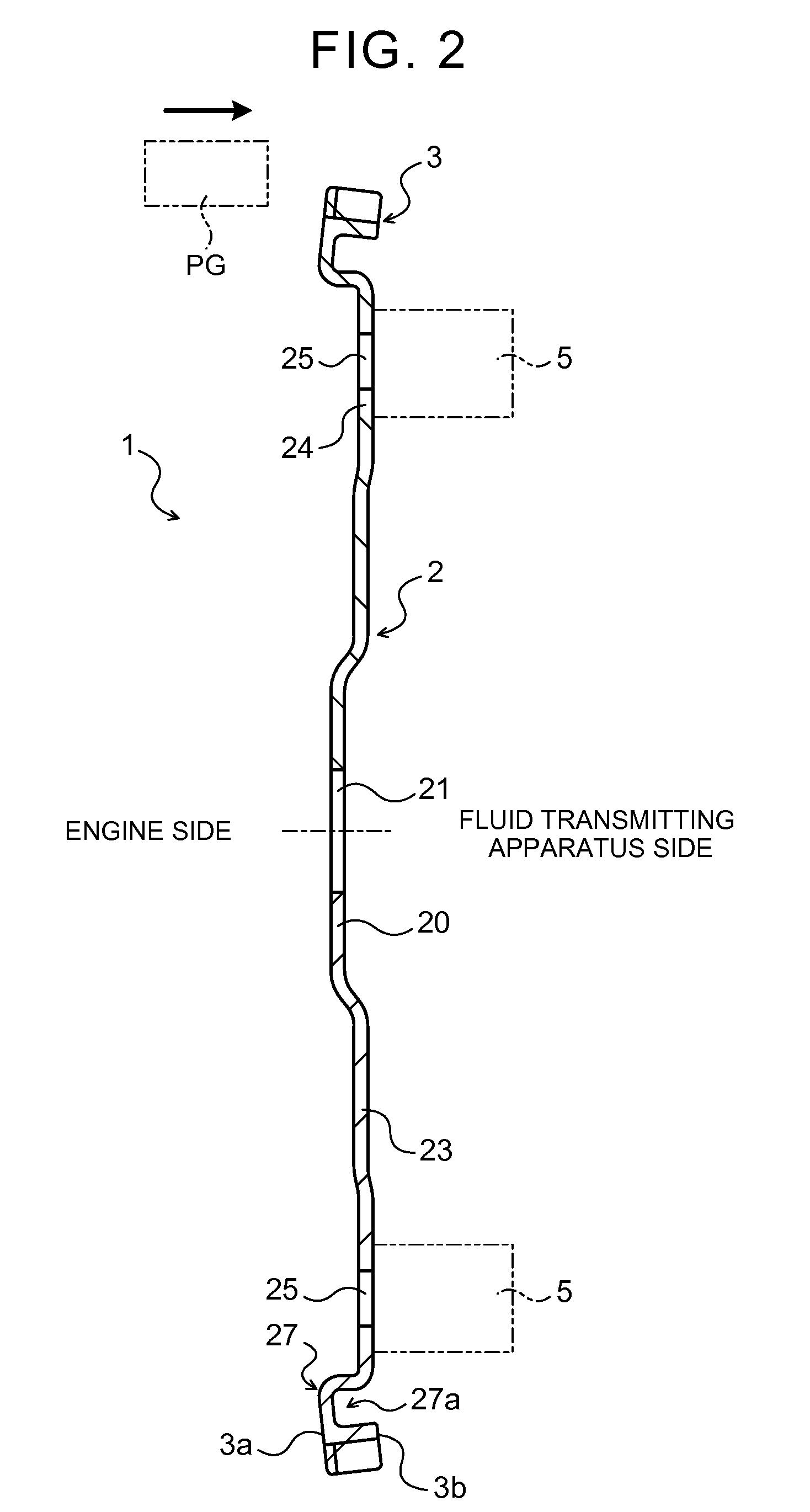
[0026]FIG. 1 is a plan view showing a drive plate 1 according to one embodiment, and FIG. 2 is a cross-sectional view taken along line II-II of FIG. 1. A drive plate 1 shown in the figures is used to transmit power output from an engine (internal combustion engine) (not shown), serving as a motor mounted on a vehicle, to a fluid transmission apparatus (not shown) such as a torque converter and a fluid coupling, which is a power transmitting subject. As shown in the figure, the drive plate 1 includes a disk-shaped plate section 2 coupled to a crankshaft of the engine and the fluid transmission apparatus, and an annular rim section (ring gear section) 3 including a plurality of teeth (external teeth) 30 that can mesh with teeth of a pinion gear PG (see FIG. 2) of a cell motor (not shown) for cranking the engine. The drive plate 1, that is, the plate section 2 and the rim section 3, are integrally molde...


PUM

PropertyMeasurementUnit
Poweraaaaaaaaaa

Abstract

A drive plate includes a plate section coupled to a crankshaft of an engine and a rim section including a plurality of teeth that meshes with a pinon gear of a cell motor for cranking the engine. The plate section and the rim section are integrally molded by press working the drive plate in an axial direction. A free end on a side opposite to a base end which is connected to the plate section of the rim section is brought closer than the base end to a central axis of the plate section, that is, the drive plate.

Description

CROSS REFERENCE TO RELATED APPLICATIONS[0001]This application is a National Stage of International Application No. PCT / JP2014 / 056947 filed Mar. 14, 2014, claiming priority based on Japanese Patent Application Nos. 2014-050246 filed Mar. 13, 2014 and 2013-052929 filed Mar. 15, 2013, the contents of all of which are incorporated herein by reference in their entirety.TECHNICAL FIELD[0002]The present subject matter relates to a drive plate that transmits power from an engine to a power transmitting subject, and a method for manufacturing the same.BACKGROUND ART[0003]Conventionally, for this type of drive plate, a drive plate is known in which a plate section and a ring gear section (rim section) are integrally molded by press working, the plate section being coupled to a crankshaft of an engine and being coupled to a torque converter, which is a power transmitting subject, via a set block, and the ring gear section including a plurality of teeth that meshes with a pinion gear of a motor...

Claims


Application Information

Patent Timeline
IPC IPC(8): F16H55/06F16H55/17B21K1/30
CPCF16H55/17F02N15/06B21D53/28B21K1/30F16H55/06
Inventor MOMIYAMA, NAOHISASUZUKI, AKITOMOSHIMIZU, KENKUROYANAGI, TAKAMITSUITAYAMA, KENTAKAMIMURA, MOTOAKIHONJO, SACHIOOTSUBO, TETSUYAOKUDA, TATSUSHIIZAWA, YOSHITOMOAOYAMA, TSUYOSHISHIBATA, HIROSHIHAMADA, GENNAKAMURA, MASAHIRO
Owner AISIN AW CO LTD
Why Eureka
Try Eureka