Pressure wave generating element and method for producing the same

Pending Publication Date: 2022-06-02
MURATA MFG CO LTD
View PDF0 Cites 0 Cited by
  • Summary
  • Abstract
  • Description
  • Claims
  • Application Information

AI Technical Summary

Benefits of technology

The present invention provides a pressure wave generating element with improved sound pressure and suitable electric resistance. This is achieved by using a heat generating layer with a fiber and a partial metal coating on the surface, which increases the surface area in contact with the air and improves sound pressure. The use of metal material also allows for the electric resistance of the heating element film to be set to an appropriate value.

Problems solved by technology

Therefore, a considerably high drive voltage is required to generate a required amount of heat generation, and it is difficult to put the drive circuit into practical use.
In addition, the carbon nanotube itself is considerably expensive and difficult to handle.

Method used


Image

  • Pressure wave generating element and method for producing the same
  • Pressure wave generating element and method for producing the same
  • Pressure wave generating element and method for producing the same

Examples


first exemplary embodiment

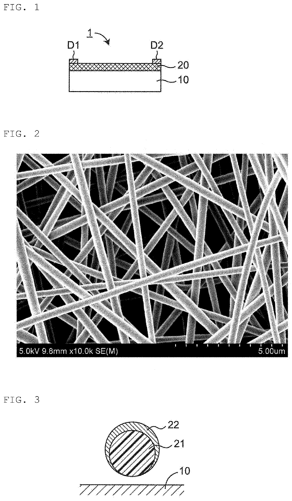
[0042]FIG. 1 is a sectional view illustrating an example of a pressure wave generating element 1 according to a first exemplary embodiment.

[0043]As shown, the pressure wave generating element 1 includes a support 10, a heat generating layer 20, and a pair of electrodes D1 and D2. The support 10 is formed of a semiconductor such as silicon or an electrical insulator such as glass, ceramic, or a polymer. A heat insulating layer having a lower thermal conductivity than that of the support 10 is provided on the support 10, so that heat dissipation from the heat generating layer 20 to the support 10 is suppressed. As described later, when the heat generating layer 20 has a heat insulating function, the above-described heat insulating layer may be omitted in an exemplary aspect.

[0044]The heat generating layer 20 is provided or disposed on the support 10. The heat generating layer 20 is formed of a conductive material, is electrically driven to generate heat by flowing a current, and emits...

second exemplary embodiment

[0051]FIG. 6 is a flowchart illustrating an example of a method for producing a pressure wave generating element according to an exemplary aspect. First, in step S1, the support 10 is prepared.

[0052]Next, in step S2, a fiber membrane is formed on the support 10 using fibers obtained by spinning. As a spinning method, a melt blowing method, a flash spinning method, a centrifugal spinning method, a melt spinning method, or the like can be employed. Further, a method in which pulp is crushed and processed into a sheet like a cellulose nanofiber can be employed. In particular, when the electrospinning method is used, nanofibers, submicron fibers, micron fibers, and the like can be realized. The spun fibers can be arranged directly on the support 10 in the form of a nonwoven fabric, or can be arranged on the support 10 in the form of a woven fabric combining warp and wefts, or in the form of a knitted fabric in which fibers are knitted.

[0053]Next, in step S3, a metal coating is applied o...

example 1

[0055](Sample Preparation Method)

[0056]A pressure wave generating element was produced by the following method (Sample 1).

[0057]A polyvinylidene fluoride (PVDF) solution prepared using a mixed solvent of N,N-dimethylformamide (DMF) and acetone (DMF:acetone=6:4) as a solvent was used as a spinning solution. The solution concentration was adjusted to 10 wt %.

[0058]Using this solution, PVDF fibers were spun on a Si substrate (675 μm thick) by an electrospinning method to form a fiber membrane of a nonwoven fabric. In order to enhance the adhesiveness between the fiber membrane and the support, an adhesive layer such as a phenoxy resin may be appropriately introduced into the interface between the Si substrate and the fiber membrane. A natural oxide film (SiO2) was formed on the surface of the Si substrate.

[0059]In this method, the electrospinning conditions were an applied voltage of 20 kV, a distance of 15 cm between a nozzle and the support, and a film formation time was adjusted so ...


PUM


Abstract

A pressure wave generating element is provided that includes a support and a heat generating layer that is provided on the support and generates heat by energization. Moreover, the heat generating layer includes a fiber with at least a partial metal coating on a surface.

Description

CROSS REFERENCE TO RELATED APPLICATIONS[0001]The present application is a continuation of PCT / JP2020 / 027447 filed Jul. 15, 2020, which claims priority to Japanese Patent Application No. 2019-158289, filed Aug. 30, 2019, the entire contents of each of which are incorporated herein by reference.TECHNICAL FIELD[0002]The present invention relates to a pressure wave generating element that generates a pressure wave by periodically heating air. In addition, the present invention also relates to a method for producing a pressure wave generating element.BACKGROUND[0003]In general, a pressure wave generating element is also referred to as a thermophone, and as an example, a resistor layer is provided on a support. When a current flows through the resistor, the resistor generates heat, and the air in contact with the resistor is thermally expanded, and subsequently, when energization is stopped, the expanded air contracts. Such periodic heating generates sound waves. When a drive signal is se...

Claims


Application Information

Patent Timeline
IPC IPC(8): H04R23/00H04R7/16H04R31/00H04R7/04
CPCH04R23/002H04R7/16H04R2307/029H04R7/04H04R2307/025H04R31/003B06B1/02
Inventor FUKAMACHI, KOHEI
Owner MURATA MFG CO LTD
Why Eureka
Try Eureka