Modular LED lighting systems, including flexible, rigid, and waterproof lighting strips and connectors

a module-type, led lighting technology, applied in the direction of lighting support devices, light source combinations, coupling device connections, etc., can solve the problems of difficult installation or repair of lighting, time-consuming, and huge conflicts, and achieve convenient interconnection, convenient repair, and adaptability.

Active Publication Date: 2015-12-31
US VAOPTO
View PDF1 Cites 8 Cited by
  • Summary
  • Abstract
  • Description
  • Claims
  • Application Information

AI Technical Summary

Benefits of technology

[0014]In light of the problems described above, embodiments of the present invention provide flexible or rigid strip lighting devices, including waterproof or water-resistant devices, that can be combined and conveniently interconnected to form modular lighting systems. Embodiments comprising flexible lighting strips are additionally readily adaptable at the time of installation for various applications and can be repaired quickly and easily when light source failures occur or changes to the lighting system are desired.
[0015]Should one or more LED of a lighting strip in a lighting system fail or otherwise need to be replaced, according to embodiments of the invention the entire strip can be removed easily from the system and a new or replacement strip can be inserted in its place. No additional components, such as socket- or plug-type connectors, are needed. Thus, repairs to previously installed lighting can be performed quickly and easily without cutting the installed strip, and / or without measuring a replacement section for the precise length of lighting strip needed for a repair, and / or without fumbling with additional component pieces for re-establishing the circuit.

Problems solved by technology

It is, however, time consuming and difficult to install or repair lighting in places where the technician may not be able to observe where and how the lighting components are installed, but instead must rely only on his hands in the placement of the components.
This conflicts tremendously, however, with the desire to minimize downtime for installation and repair of such systems so as not to disrupt the operating schedule of a particular commercial establishment.
Further, some types of installations would be impossible to perform in certain circumstances or otherwise extremely time consuming so as not to warrant the repair or installation.
As can be imagined, it is especially difficult if not impossible to make this kind of repair in places where the technician can only use his hands, not his eyes, during the repair.
For example, without a visual inspection it would be very difficult to determine where to make the needed cuts.
Instead, a larger section of the lighting most likely would have to be removed from its point of installation, repaired, and then re-installed, which is burdensome and takes more time leading to longer overall repair times.
For low-profile lighting in hard to reach places, it is cumbersome for the technician to orient the individual connectors in the correct position without visual assistance because the connectors are often too tiny to be able to discern surface differences with only the fingers.
Determining proper alignment in these cases is often difficult and time consuming.
Having multiple junctions, however, can increase the opportunity for lighting failures, as each junction provides a place where the circuit can be broken, e.g., when the components become loose over time and ultimately disconnected.
Likewise, the amount of time needed for troubleshooting such types of lighting strip failures is proportional to the number of components in the system, so reducing the number of components can save on repair troubleshooting time.
Lighting devices exposed to moisture and / or extreme temperatures, however, is often at risk for failure.
If moisture, especially water droplets, is allowed to contact non-waterproof lighting devices, the water can cause a short circuit or other electrical failure of the device, requiring repair and / or replacement of the failed components.
By not covering the LEDs, however, there is an increased chance of moisture being introduced into the system where the colloid layer meets the LEDs.
Further, in some situations, epoxy resin as colloid layer has been found to be inadequate, such as in extreme temperature situations, including in external weather or environmental conditions or due to the use of high brightness LEDs, which typically have a high heat output during operating of such devices.
Under extreme low or high temperatures epoxy resin can craze or become discolored or cloudy, leading to cracks in the waterproof barrier and a decrease in the amount of light output from the device.
For example, lighting strips that are waterproof, are configured to be cut to a desired length during installation, minimize the number of electrical junctures for a lighting strip system, can be cut and re-connected by way of a waterproof connector, and / or are adaptable to remain waterproof after cutting would be highly desirable, however, existing lighting strip devices and assemblies do not satisfy this need.
Although lighting systems have been somewhat successful, known lighting systems have encountered certain problems.
One known problem is the excessive number of components required to make such lighting systems.
Another problem relates to the fragile nature of such lighting systems.
Often lighting systems must be individually crafted which increases the purchasing price associated with such lighting systems.
Another problem with known lighting systems relates to the lack of convenient interconnectable components of individual lighting sections and the lack of easily removable and securely fit interconnections.

Method used


Image

  • Modular LED lighting systems, including flexible, rigid, and waterproof lighting strips and connectors
  • Modular LED lighting systems, including flexible, rigid, and waterproof lighting strips and connectors
  • Modular LED lighting systems, including flexible, rigid, and waterproof lighting strips and connectors

Examples


Embodiment Construction

[0143]Reference will now be made in detail to various exemplary embodiments of the invention. The following detailed description is presented for the purpose of describing certain embodiments in detail and is, thus, not to be considered as limiting the invention to the embodiments described. Additionally, any features of any embodiment described herein are equally applicable to any other embodiment described herein or envisioned by one of ordinary skill in the art. Thus, the detailed descriptions provided herein should not be construed to exclude features otherwise described with respect to another embodiment.

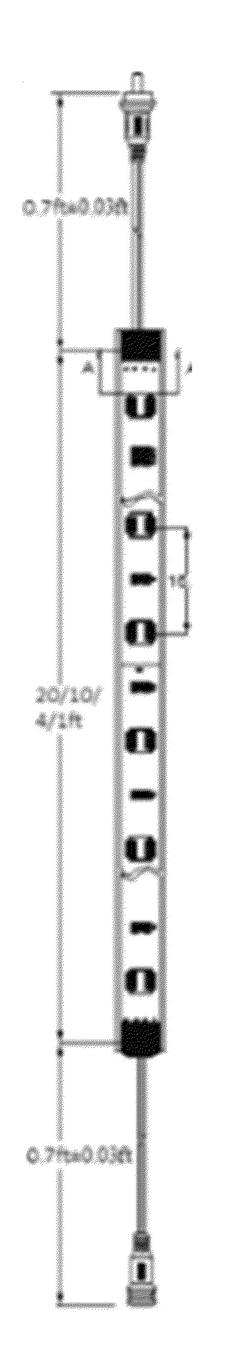
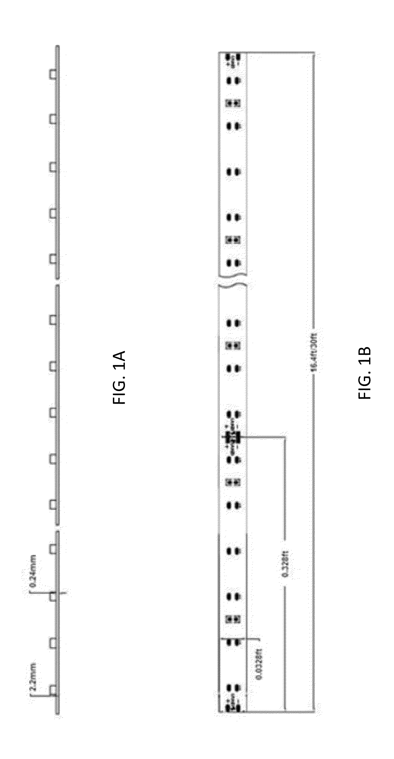
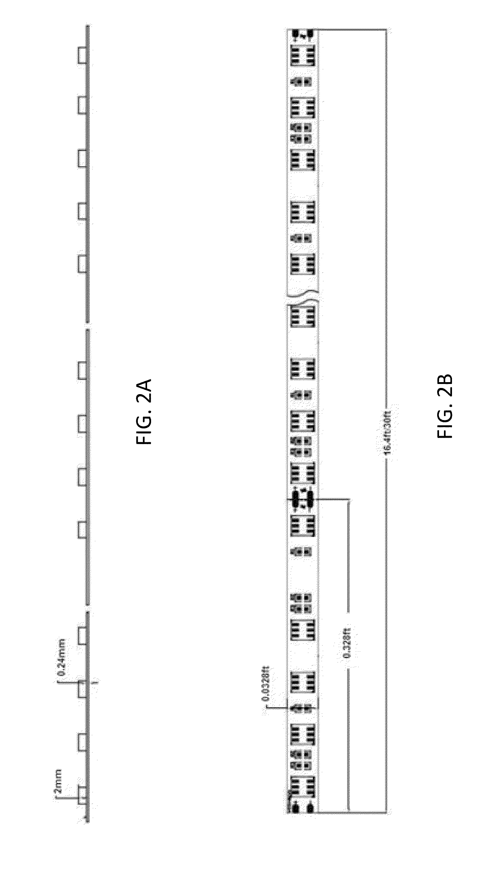
[0144]Particular embodiments according to the invention may include a modular lighting strip comprising: a non-conductive substrate strip comprising an electrical circuit; a plurality of light sources operably connected to the electrical circuit; a plug integrally formed at an end of the substrate strip; and a socket integrally formed at an opposing end of the substrate strip; ...


PUM


Abstract

Modular lighting systems are provided that comprise lighting strips physically and electrically connectable with one another by way of flexible connectors. The lighting strip devices can be made of flexible or rigid material to allow for applying the lighting devices along flat as well as contoured surfaces and can be waterproof or water resistant. A modular lighting strip system is provided comprising: two or more lighting strips comprising a non-conductive substrate strip with an electrical circuit; a plurality of light sources operably connected to the electrical circuit; a plug or socket at opposing ends of the strip; one or more connectors for providing electrical and physical interconnection of the lighting strips comprising: one or more plug and / or socket and one or more flexible wires interconnecting the plugs or sockets, which are operably configured to provide for side-by-side interconnection of lighting strips.

Description

CROSS-REFERENCE TO RELATED APPLICATIONS[0001]This application is a Continuation-in-Part (CIP) of and claims priority to and the benefit of the filing date of parent U.S. application Ser. No. 12 / 975,112, filed Dec. 21, 2010, which claims priority to and the benefit of the filing date of U.S. Provisional Application No. 61 / 288,815, filed Dec. 21, 2009, and which parent application is a CIP of U.S. application Ser. No. 12 / 499,306, filed Jul. 8, 2009, which claims priority to and the benefit of the filing date of U.S. Provisional Application No. 61 / 079,042, filed Jul. 8, 2008, the disclosures of each of which are hereby incorporated by reference herein in their entireties. This application is also a CIP of and claims priority to and the benefit of the filing date of parent U.S. application Ser. No. 13 / 106,558, filed May 12, 2011, which claims priority to and the benefit of the filing date of U.S. Provisional Application No. 61 / 333,806, filed May 12, 2010, and which parent application is...

Claims


Application Information

Patent Timeline
Patent Type & Authority Applications(United States)
IPC IPC(8): F21V21/005H01R13/52F21V31/00H01R25/00F21S4/00F21V23/06
CPCH05K2201/10189F21V23/001F21V21/005H05K1/189H05K3/284H05K2201/10106F21V23/06F21V31/00F21V21/32F21Y2113/13F21Y2101/00F21Y2103/10F21Y2115/10F21Y2113/17H01R13/5219F21V31/005H01R25/006F21S2/00F21S4/22F21S4/28F21S4/24F21V17/007
Inventor LI, CHARLES QING
Owner US VAOPTO
Why Eureka
Try Eureka