Dynamic liner sleeve for flexible coupling

a flexible coupling and dynamic liner technology, applied in the direction of adjustable joints, mechanical equipment, machines/engines, etc., can solve the problems of high failure rate of the coupling, accelerated fatigue and abrasion failure, and the nature of the diesel engine creates a very severe nvh (noise, vibration, harshness) environment, so as to reduce nvh, increase the durability of the bellow, and reduce the effect of natural vibration or frequency

Active Publication Date: 2016-01-07
AMERICAN BOA
View PDF9 Cites 9 Cited by
  • Summary
  • Abstract
  • Description
  • Claims
  • Application Information

AI Technical Summary

Benefits of technology

[0008]A preferred embodiment of this invention includes a continuous, axial spiral-pattern wound metal or non-metal sleeve around a typical liner and interposed in the coupling between a bellow and a bellow liner. The coupling is preferably used for connecting ends of two conduits or pipes and preferably pipes in an engine exhaust system. This sleeve is fully flexible and free to move dynamically in 6 degrees of freedom so it does not restrict motion of the bellow or bellow liner or other surrounding components. It functions as an insulator against internal heat transfer between the liner and the bellow as well as prevents liner to bellow contact as a result of thermally or stress induced movement. The sleeve also dampens natural vibration or frequencies of the bellow thus reduces NVH and increases bellow fatigue durability. Most importantly, it also prevents bellow to liner contact abrasion in harsh NVH environments (when high g-loads are applied to the flexible coupling).
[0009]Beneficially, the sleeve, even as it moves, maintains separation of the bellows and liner. An air gap is preferably but not always maintained between the sleeve and the bellow; the sleeve functions to dampen the bellow when contacting it, and to dampen the liner as well.
[0010]In restricting the loss of high exhaust gas temperatures, the invention increases the efficiency of ATD's used in exhaust gas systems having couplings according to the invention.

Problems solved by technology

In flexible exhaust couplings used behind a diesel engine (on-highway and off-highway) there are observed high failure rates of the couplings.
The nature of the diesel engine creates a very severe NVH (noise, vibration, harshness) environment which is detrimental to adjacent components and more specifically the flexible coupling in the exhaust system.
That leads to accelerated fatigue and abrasion failure.
Gas temperature loss in any system flexible coupling renders this process less efficient.
Thus undesirable temperature losses in the prior couplings reduce the system's efficiency in cleaning periodically.
Respecting the SCR, the chemical conversion of undesirable NOx to non-harmful chemicals like N2, H2O and CO2 requires high temperatures such as in the range of 357° C. and 447° C. Exhaust gas temperature loss in prior flexible couplings renders the conversion less efficient.
Nevertheless, such prior efforts as are known are limited to static spacers which cannot move dynamically, or which are positively connected to the bellow, or of static length, thereby of limited dynamic effect as the bellows and liner move from one configuration to another due to thermal, dynamic or assembly stresses in the coupling.

Method used


Image

  • Dynamic liner sleeve for flexible coupling
  • Dynamic liner sleeve for flexible coupling
  • Dynamic liner sleeve for flexible coupling

Examples


Embodiment Construction

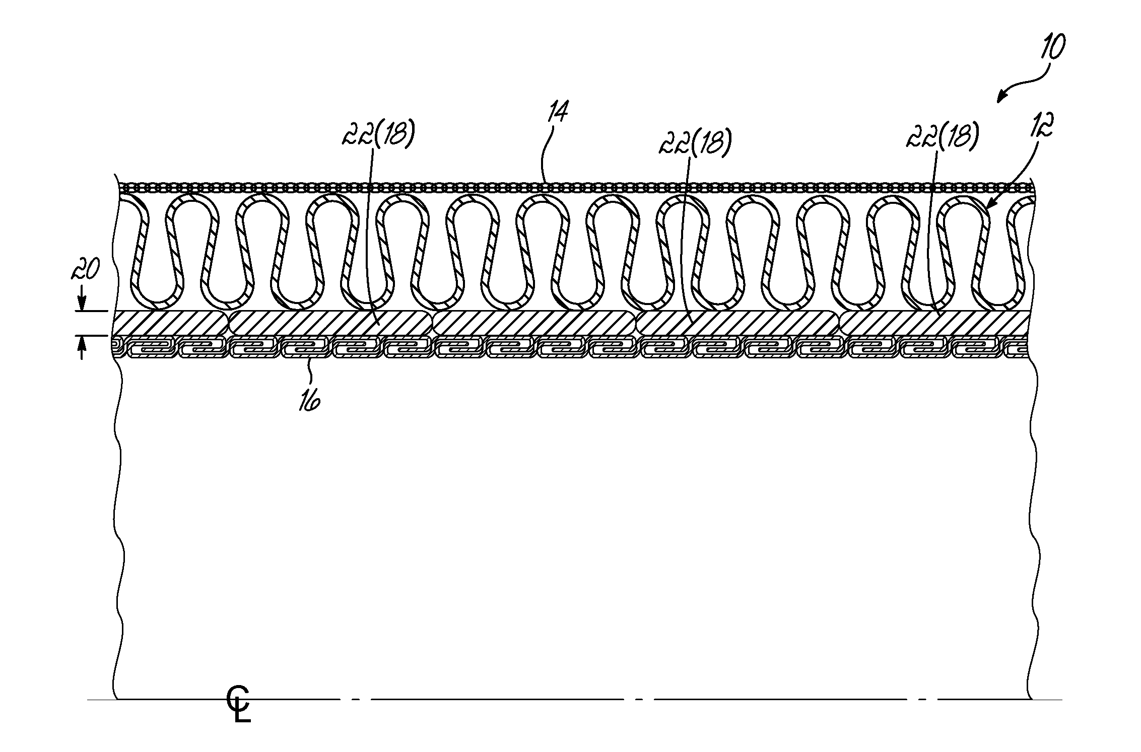
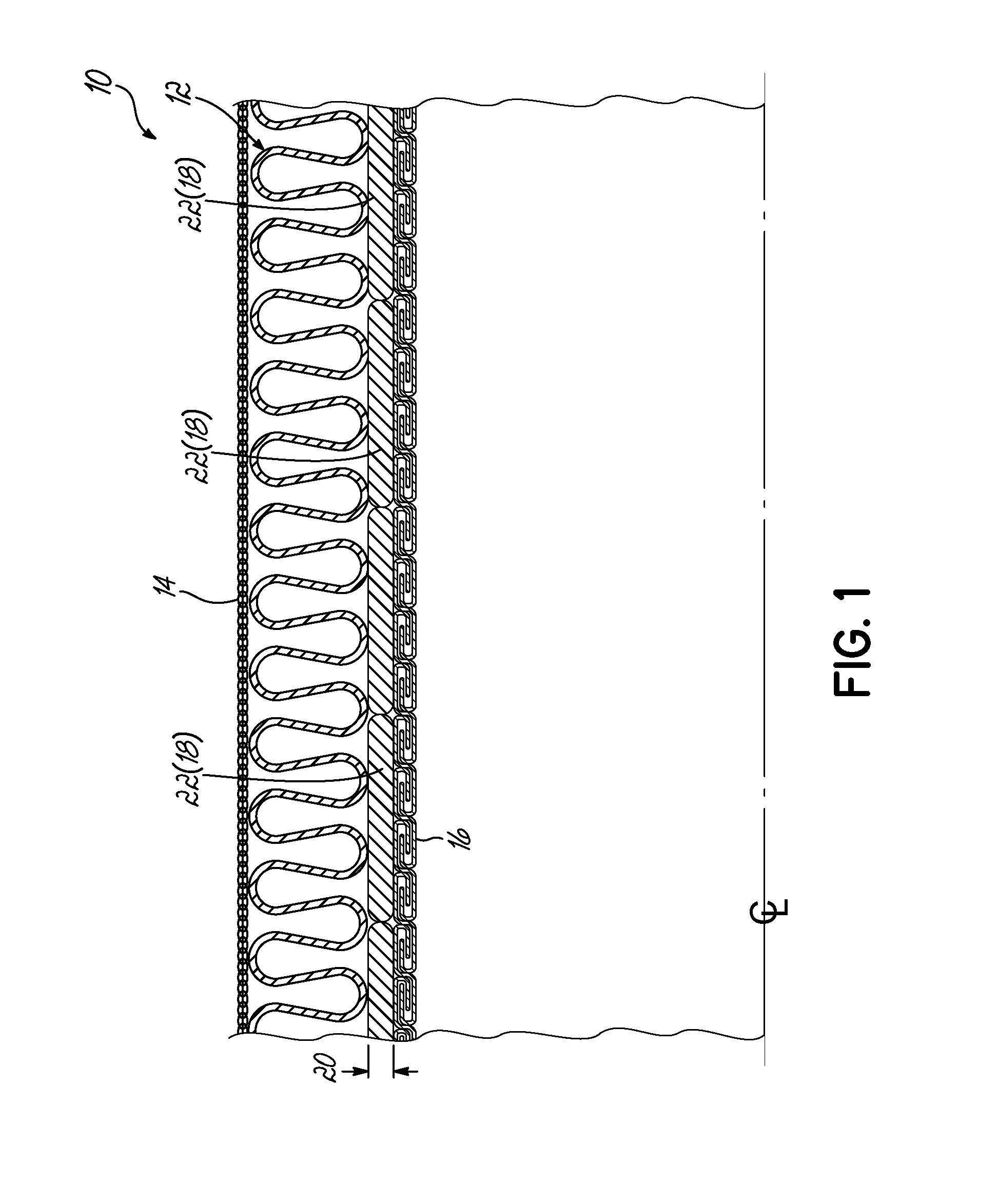
[0020]Turning to FIGS. 1 and 2, a partial cross-section of a flexible coupling 10 according to the invention is disclosed about a center line CL, defining an elongated coupling axis.

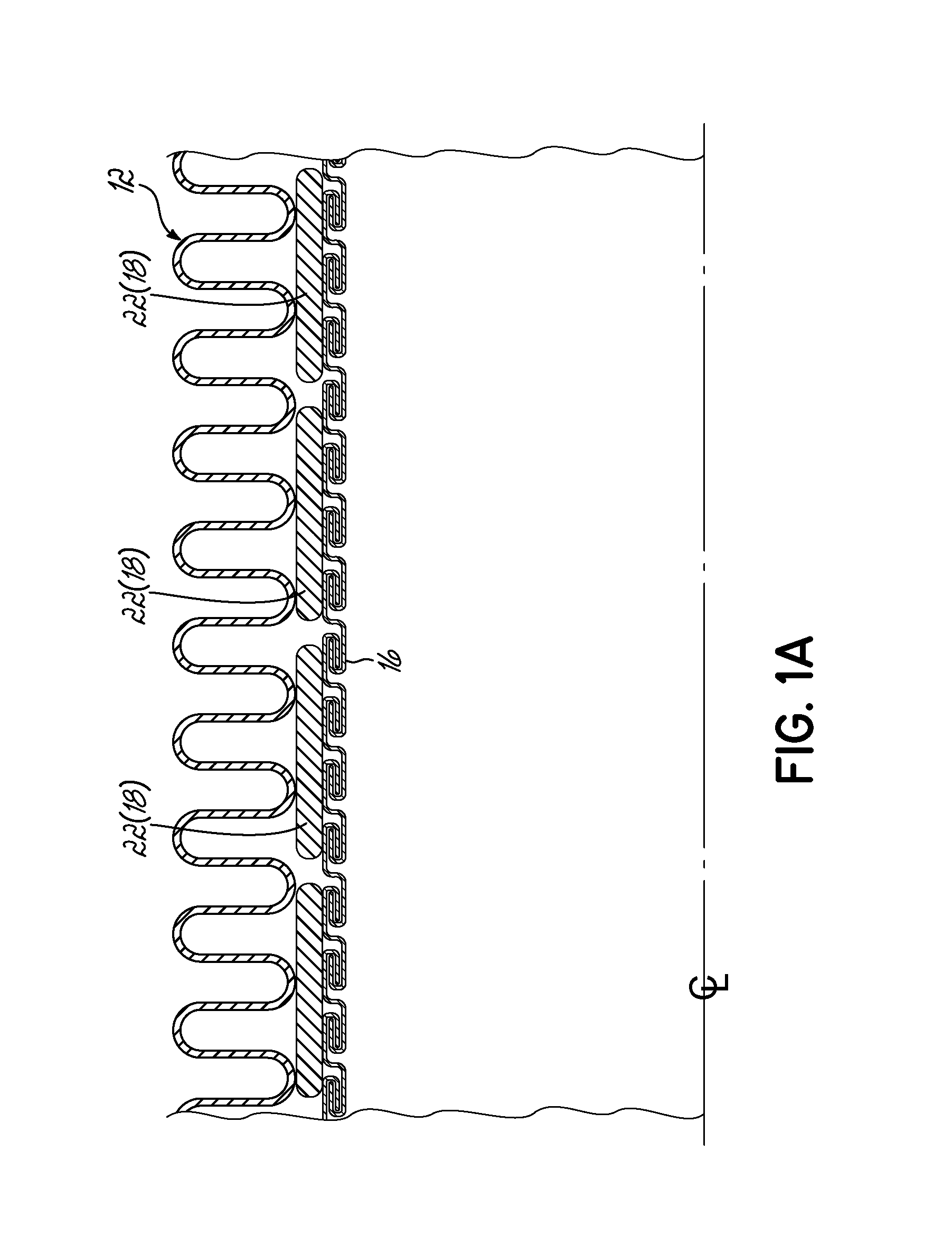
[0021]A convoluted, flexible bellow 12 (sometimes referred to as “bellows”) is covered externally by a braided outer sleeve 14 as typical in the industry. The coupling 10 is provided with an internal liner 16 extending axially and internally of coupler 10 as shown and, finally, according to the invention, a flexible, dynamic liner sleeve 18 is spirally wound about liner 16. Liner 16 is preferably formed from an interlocked strip as indicated in FIG. 1A.

[0022]It will be appreciated that in the past, liner 16 and bellow 12 could be adjacent and could touch (see FIG. 7). Respective vibration could occur between the two, causing contact abrasion, producing noise, heat conduction and other undesirable artifacts.

[0023]According to the invention, spiral wound liner sleeve 18 is disposed about the liner 16, prov...


PUM


Abstract

A flexible coupling includes a liner, a bellow, and a liner sleeve preferably defined by a compressed woven mesh strip spirally wound around the liner between bellow and liner and moveable longitudinally with respect to the bellow and liner when the coupling expands linearly. An alternate sleeve in the form of a cylinder is disposed about the liner, under the bellow and is formed of a woven non-compressed mesh.

Description

PRIORITY CLAIM[0001]Applicant claims the benefit of the filing date of U.S. Provisional Patent Application Ser. No. 62 / 020,096, filed Jul. 2, 2014, which application is expressly incorporated herein by reference.FIELD OF THE INVENTION[0002]This invention relates to flexible couplings used for coupling tubes and pipes and more particularly to flexible couplings used in exhaust systems for internal combustion engines, other harsh, corrosive applications and the like.BACKGROUND OF THE INVENTION[0003]In flexible exhaust couplings used behind a diesel engine (on-highway and off-highway) there are observed high failure rates of the couplings. The nature of the diesel engine creates a very severe NVH (noise, vibration, harshness) environment which is detrimental to adjacent components and more specifically the flexible coupling in the exhaust system. Such systems typically have a low spring stiffness bellow having a low natural frequency that easily aligns with the vibration profile of the...

Claims


Application Information

Patent Timeline
Patent Type & Authority Applications(United States)
IPC IPC(8): F16L27/11F16L21/00F16L51/02
CPCF16L27/11F16L21/00F16L51/025F01N13/1816F16L27/111F16L27/1004F16L51/026F16L51/027
Inventor BARBELY, ERICJANSSEN, ROLFGADE, SRINIVAS
Owner AMERICAN BOA
Why Eureka
Try Eureka