Electronic management system for electricity generating cells, electricity generating system and method for electronically managing energy flow

a technology of electronic management system and electricity generating cell, which is applied in the direction of d semiconductor device, ac network circuit arrangement, etc., can solve the problems of multiple micro-converters, multiple micro-inverters, and only solving a part of photovoltaic panels, and achieves significant power loss in shaded and non-shaded modules, and achieves cost increas

Active Publication Date: 2016-01-07
TOTAL MARKETING SERVICES SA +1
View PDF9 Cites 15 Cited by
  • Summary
  • Abstract
  • Description
  • Claims
  • Application Information

AI Technical Summary

Problems solved by technology

In this configuration, shading by chimneys, trees, power lines, soiling from dust, debris, and bird droppings, (and also panels' mismatch due to manufacturing tolerance, ageing, etc.) can cause significant power losses in both shaded and non-shaded modules.
However, this association of multiple micro-converters, or micro-inverters, can only solve a part of the problems related to partial shadowing and different tilt or orientation angles of photovoltaic modules.
In addition, the increasing number of micro-converter results in a cost increase of such photovoltaic panels.
However, the solution in this document is cumbersome and expensive as routing as well as switching takes place between the solar cells on the substrate.
In addition, not only routing lines for energy flow, but also control lines for controlling the transistors have to be foreseen which will render solar panels more expensive.
Thus reconfiguration and therefore converter capacities are not used in an optimized manner.
Although this document discloses to realize a serial / parallel connection in order to supply to the input of the converters current in their working range, the solution in this document does not allow taking into account efficiently the whole chain from the PV cell to the output of the converters.

Method used


Image

  • Electronic management system for electricity generating cells, electricity generating system and method for electronically managing energy flow
  • Electronic management system for electricity generating cells, electricity generating system and method for electronically managing energy flow
  • Electronic management system for electricity generating cells, electricity generating system and method for electronically managing energy flow

Examples


Embodiment Construction

[0090]On all the figures the same references refer to the same elements.

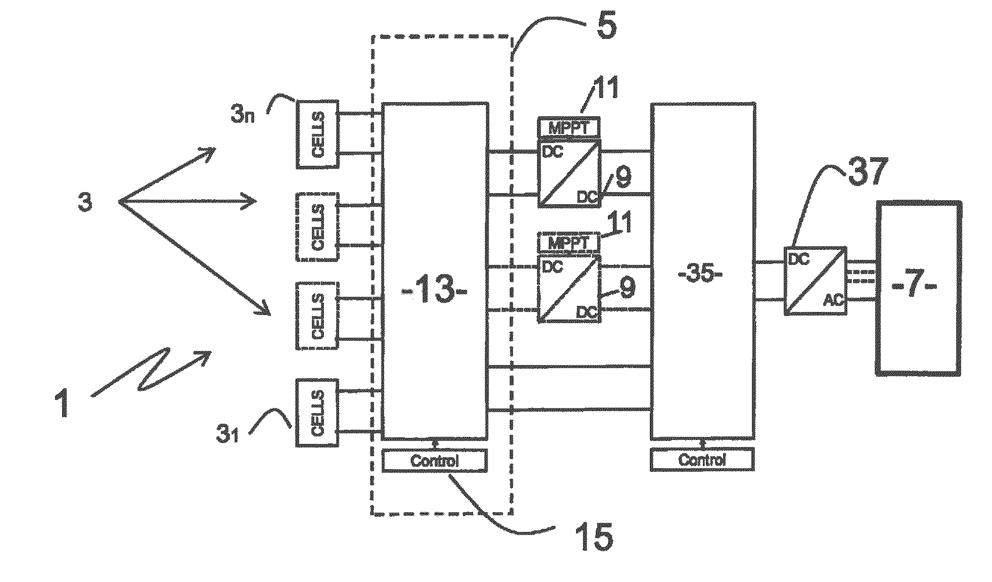
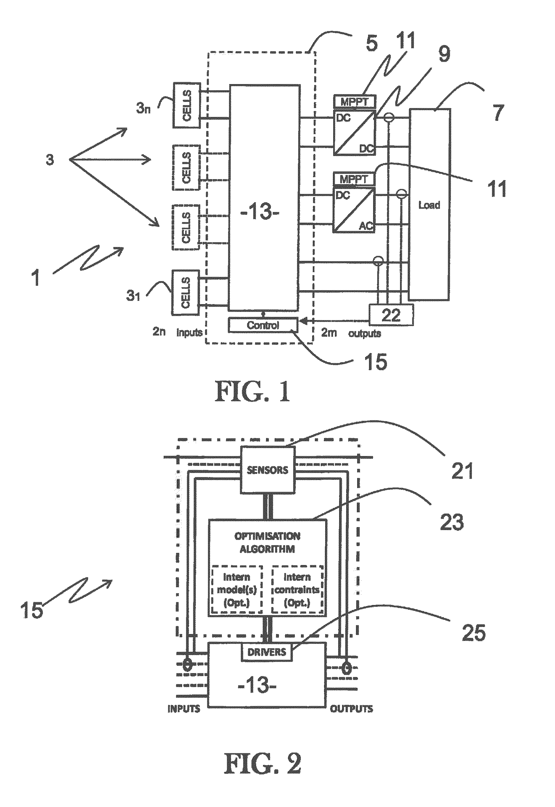
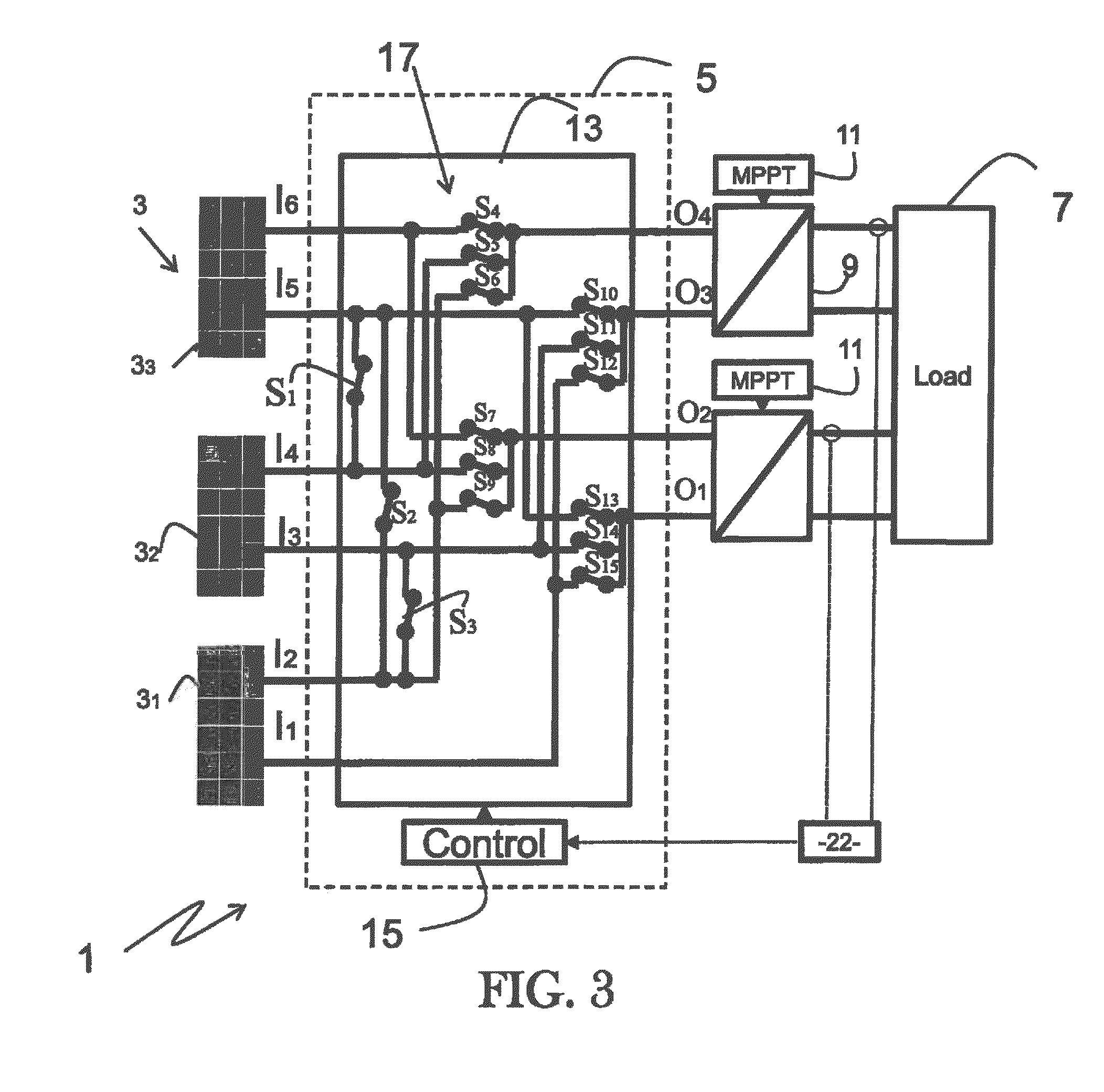
[0091]FIG. 1 schematically illustrates an electricity generating system 1 comprising electricity generating cells 3 (31, 32, 33, . . . 3n; n being a positive integer).

[0092]Such electricity generating cells 3 may be photovoltaic cells (PV cells), photovoltaic strings comprising several PV cells, electrochemical cells, fuel cells or any part of a modular electricity generator.

[0093]The following description focuses more specifically on PV cells and PV strings, but does not exclude other sources of renewable electric energy or electrical storage devices.

[0094]In the case of inorganic materials, a photovoltaic cell essentially consists of a diode (pin or pn junction) made up from a semiconductor material. This material has the property of absorbing light energy, a significant portion of which may be transferred to charge carriers (electrons and holes). With the structure of a diode (pin or pn junction)—with doping ...


PUM


Abstract

The invention relates to an electronic management system (5) for electricity generating cells (3), the system comprising:
cell connection terminals to be connected to n associated electricity generating cells (3), n being a positive integer number,
outputs to be connected to m associated static converters (9); m being a positive integer number and at least m=2,
an energy routing module (13) adapted for routing energy flows from and between said cell connection terminals towards said outputs; and
an electronic control unit (15) adapted for controlling dynamically the energy routing module (13).

Description

FIELD OF THE INVENTION[0001]The present invention relates to the field of electricity generating cells such as photovoltaic generators and more specifically to an electronic management system for electricity generating cells, an electricity generating system and a method for electronically managing energy flow.BACKGROUND AND PRIOR ART[0002]Standard photovoltaic installations comprise in general a centralized converter which has typically only one input channel able to perform individual Maximum Power Point Tracking (MPPT).[0003]Photovoltaic modules are made of several strings of cells (for example 3 strings in a panel). A string of cells is the serial connection of several photovoltaic cells (for example 32 cells per string in one panel). These strings of cells are serial connected in the photovoltaic junction-box.[0004]To each of these strings a by-pass diode can be associated in the photovoltaic junction box. These by-pass diodes aim to prevent damaging of photovoltaic cells when ...

Claims


Application Information

Patent Timeline
Patent Type & Authority Applications(United States)
IPC IPC(8): H02J3/38
CPCH02J3/383H01L31/02021Y02E10/56Y02E10/50
Inventor RAMOND, ADRIENCARREJO, CARLOSEL BASRI, YOUSSEFALONSO, CORRINEESTIBALS, BRUNOSEGUIER, LIONEL
Owner TOTAL MARKETING SERVICES SA
Why Eureka
Try Eureka