Illuminating device, image reading device, and image forming device including the illuminating device and the image reading device

a technology of image reading and illumination device, which is applied in the direction of fibre light guides, lighting and heating apparatus, instruments, etc., can solve the problems of uneven amount of light thrown on the subject, insufficient lengthwise strength of light-guiding member, and inability to achieve uniform illumination of the subject, so as to minimize the warpage of long light-guiding member, accurately and easily positioned, the effect of illuminated subj

Active Publication Date: 2016-01-07
SHARP KK
View PDF8 Cites 8 Cited by
  • Summary
  • Abstract
  • Description
  • Claims
  • Application Information

AI Technical Summary

Benefits of technology

[0009]It is desirable to provide an illuminating device, an image reading device, and an image forming device including the illuminating device and the image reading device that can minimize warpage of a long light-guiding member while the light-guiding member is allowed to be accurately and easily positioned and that can illuminate a subject with a uniform amount of light.

Problems solved by technology

However, the light-guiding member according to Japanese Unexamined Patent Application Publication No. 10-190959 that has multiple integrated protrusions has the following problem.
Measures taken to prevent an occurrence of an area from which light is thrown in an uneven amount may disadvantageously impair the design freedom in terms of, for example, the positions or the shapes of the protrusions.
Since having a long shape, the lengthwise strength of the light-guiding member is insufficient.
Thus, the light-guiding member is more likely to bend due to, for example, vibrations resulting from scanning during a reading operation, the bending or warpage disturbs light transmission through the light-guiding member, and an uneven amount of light may be thrown on the subject from some area of the light emerging surface.

Method used


Image

  • Illuminating device, image reading device, and image forming device including the illuminating device and the image reading device
  • Illuminating device, image reading device, and image forming device including the illuminating device and the image reading device
  • Illuminating device, image reading device, and image forming device including the illuminating device and the image reading device

Examples


first embodiment

[0029]Referring now to the drawings, an embodiment of the disclosure is described in detail below. Firstly, examples of the structures of a document reading device and an image forming device according to an embodiment of the disclosure are described.

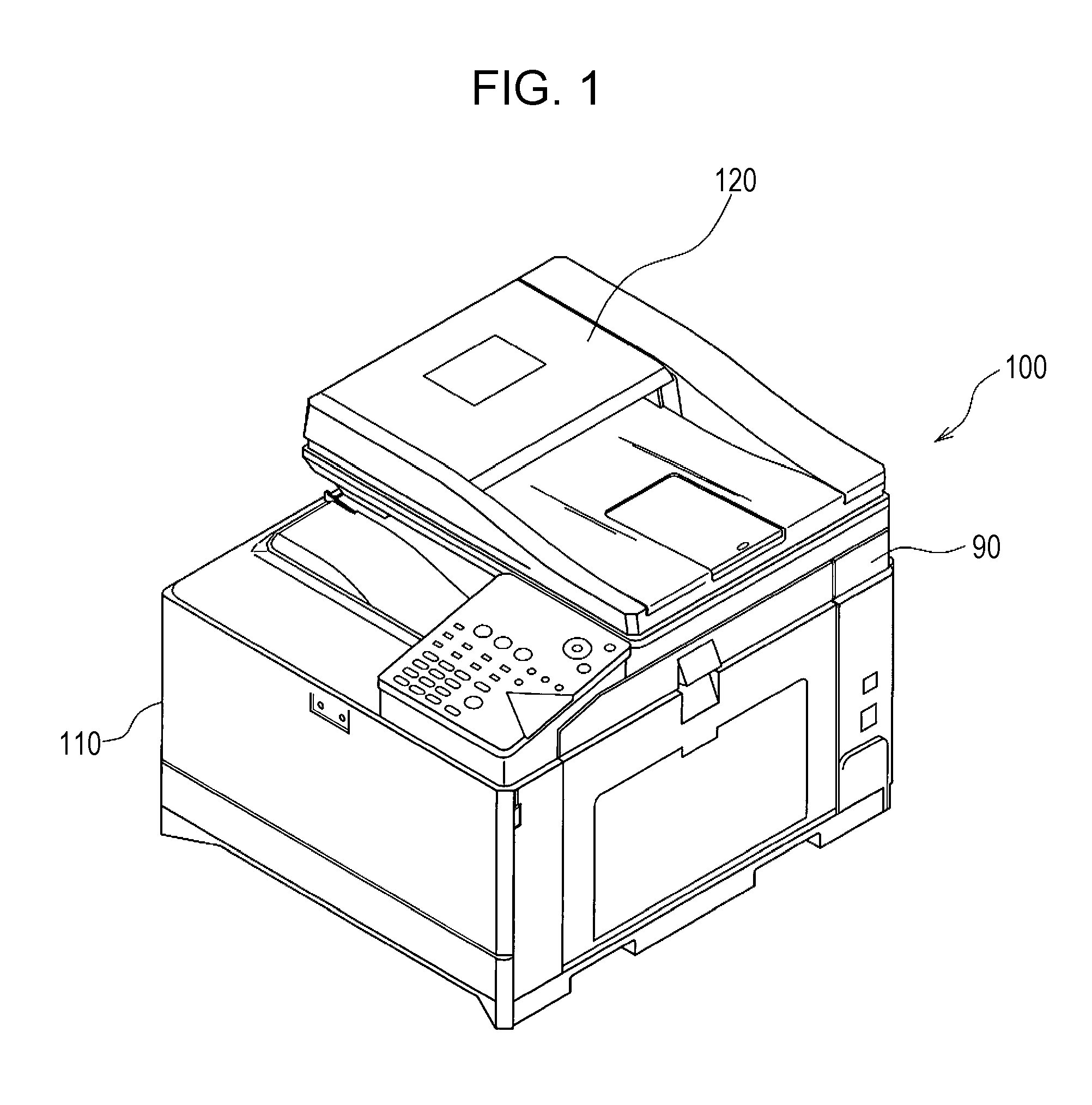
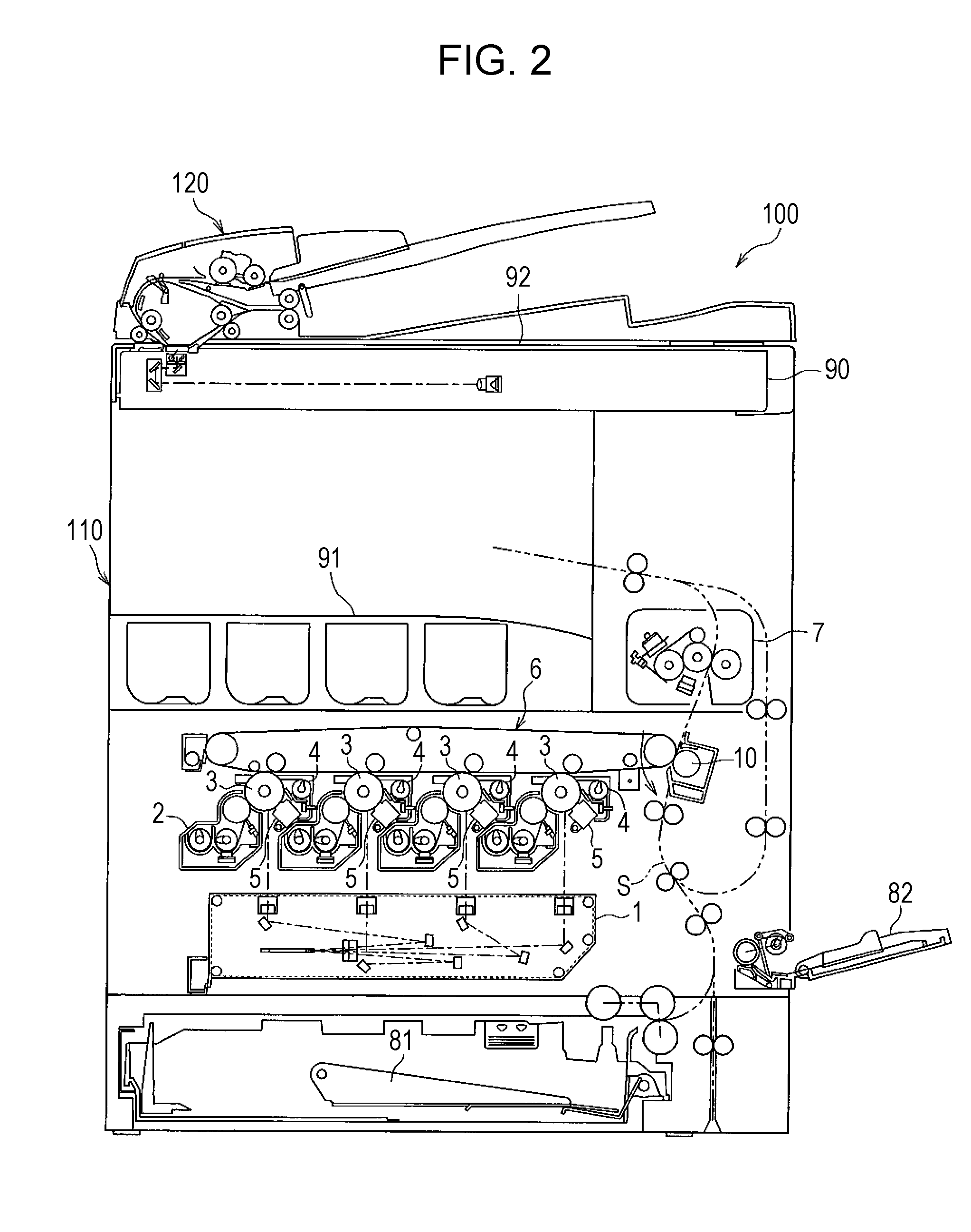
[0030]FIG. 1 is a schematic perspective view of an image forming device 100 according to an embodiment of the disclosure. FIG. 2 is a rough cross-sectional view of the image forming device 100 according to an embodiment of the disclosure. The image forming device 100 includes a device body 110 and an automatic document feeder 120. The device body 110 includes a document reading portion 90, which reads images of documents, and a document receiving table 92, on which documents are placed.

[0031]The document reading portion 90 is disposed at an upper portion of the device body 110. The document receiving table 92 is made of a transparent glass and disposed above the document reading portion 90. The automatic document feeder 120 is disposed ...

second embodiment

[0074]Now, a second embodiment of the disclosure is described. Components that are the same as those in the first embodiment are not described. FIGS. 14A to 14C are schematic perspective views of light-guiding members 130 according to the second embodiment. FIG. 14A is a general perspective view of the light-guiding members 130 according to the second embodiment. FIG. 14B is a partially-enlarged perspective view of end portions of the light-guiding members 130 illustrated in an enlarged manner. FIG. 14C is a partially-enlarged perspective view of lengthwise middle portions of the light-guiding members 130 illustrated in an enlarged manner.

[0075]As illustrated in FIGS. 14A to 14C, the light-guiding members 130 according to the second embodiment respectively include gates 130c and 130e, having a predetermined width in the main-scanning direction, in substantially the middle portions of the long, substantially cylindrical translucent bodies 130a. The light-guiding members 130 also incl...

third embodiment

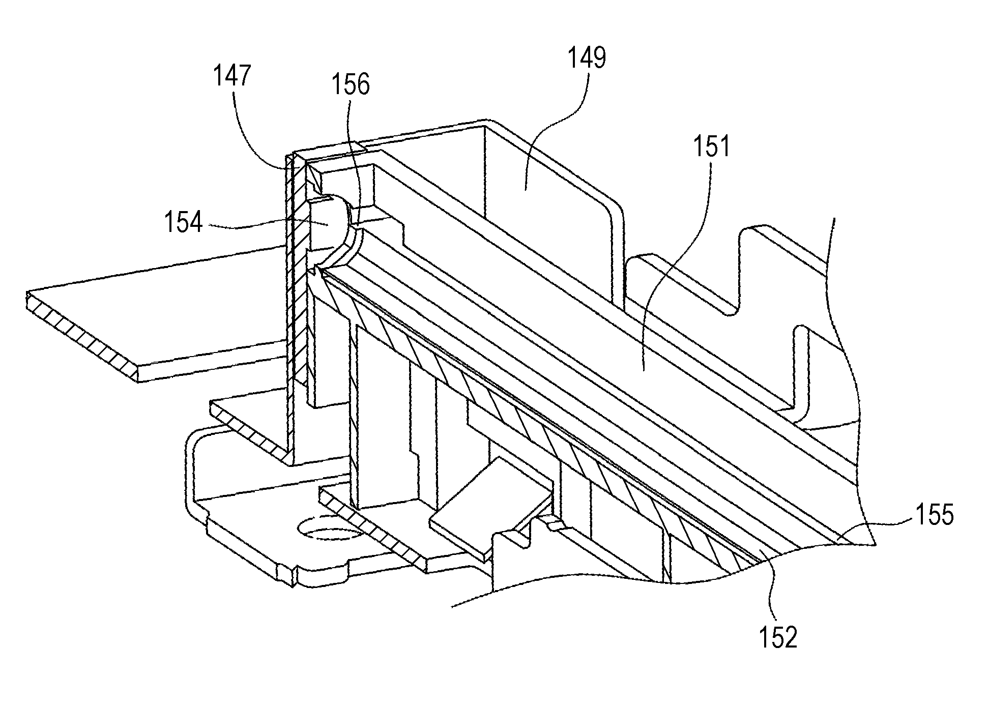
[0080]The first embodiment has described a case where the light source unit 140 includes two light-guiding members 130. However, one light-guiding member 130 and one attachment recess 152 suffice for the light source unit 140. As in the case of the other embodiments, holes 153c and 153d are formed in the wall portion 151 of the holder member 150. Thus, inserting and fitting the gate 130c and the protrusion 130d of the light-guiding member 130 into the holes 153c and 153d can minimize warpage of the light-guiding member 130 while the light-guiding member 130 is accurately and easily positioned and light can be thrown on a subject in a uniform amount.

[0081]The disclosure is not limited to the embodiments described above. The disclosure may be modified in various manners within the range of claims. Embodiments obtained by appropriately combining techniques disclosed in different embodiments are also included in the technical range of the disclosure.


PUM


Abstract

In an image forming device, a light-guiding member includes an integrated ridge extending in the longitudinal direction of the light-guiding member. The light-guiding member further includes a protrusion on the ridge. The illuminating device includes an attachment recess that holds the light-guiding member and a holder member that has a fit portion to which a protrusion is fitted. The protrusion is disposed at a position decentered to one end portion of the light-guiding member in the longitudinal direction of the light-guiding member.

Description

BACKGROUND[0001]1. Field[0002]The present disclosure relates to an illuminating device, an image reading device, and an image forming device including the illuminating device and the image reading device.[0003]2. Description of the Related Art[0004]Typical image reading devices read a document by repeatedly scanning the document in a main-scanning direction using an image sensor, such as a charge coupled device (CCD), while transporting the document over a glass plate in a sub-scanning direction and illuminating the document using a light source unit under the glass plate or while keeping the document fixed at a determined position on the glass plate, moving components such as the light source unit and the image sensor in the sub-scanning direction under the glass plate, and illuminating the document using the light source unit. Examples usable as the light source unit that illuminates a document include various types such as a fluorescent light or a LED array.[0005]In such image re...

Claims


Application Information

Patent Timeline
Patent Type & Authority Applications(United States)
IPC IPC(8): H04N1/028F21V8/00
CPCG02B6/0073H04N1/02835H04N1/02855G02B6/0006G02B6/0088H04N2201/0081
Inventor SUTO, YASUHIRONAKANISHI, KENJIFUKUTOME, SHOHICHIIMOTO, MASAHIROIGUCHI, KAZUHIROKURUMA, HIROKI
Owner SHARP KK
Why Eureka
Try Eureka