Illumination and grow light system and associated methods

Active Publication Date: 2016-01-07
BIOLOGICAL ILLUMINATION
View PDF12 Cites 41 Cited by
  • Summary
  • Abstract
  • Description
  • Claims
  • Application Information

AI Technical Summary

Benefits of technology

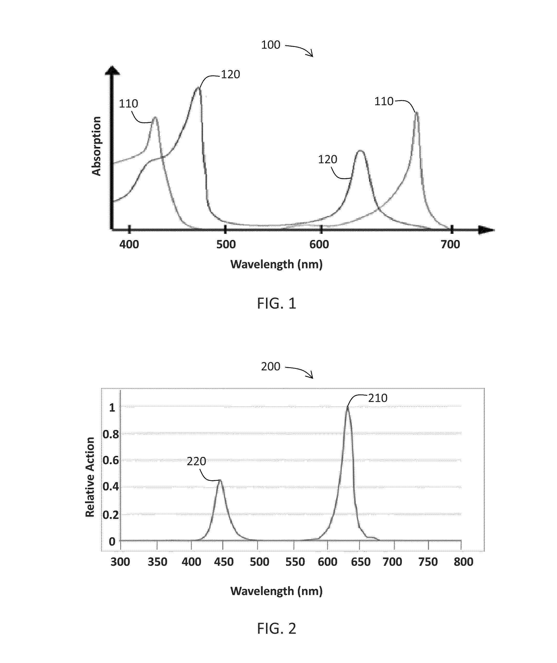
[0010]With the foregoing in mind, embodiments of the present invention are related to systems and methods for producing light which is optimized for plant growth, spectral sensitivity, and energy efficiency. In one embodiment, red light generated by the luminaire according to an embodiment of the present invention may advantageously stimulate photosynthesis, overlapping well with the plant response curve while not overlapping the human photopic response curve. In yet another embodiment, the luminaire according to an embodiment of the present invention may advantageously produce a spectrum of light optimi

Problems solved by technology

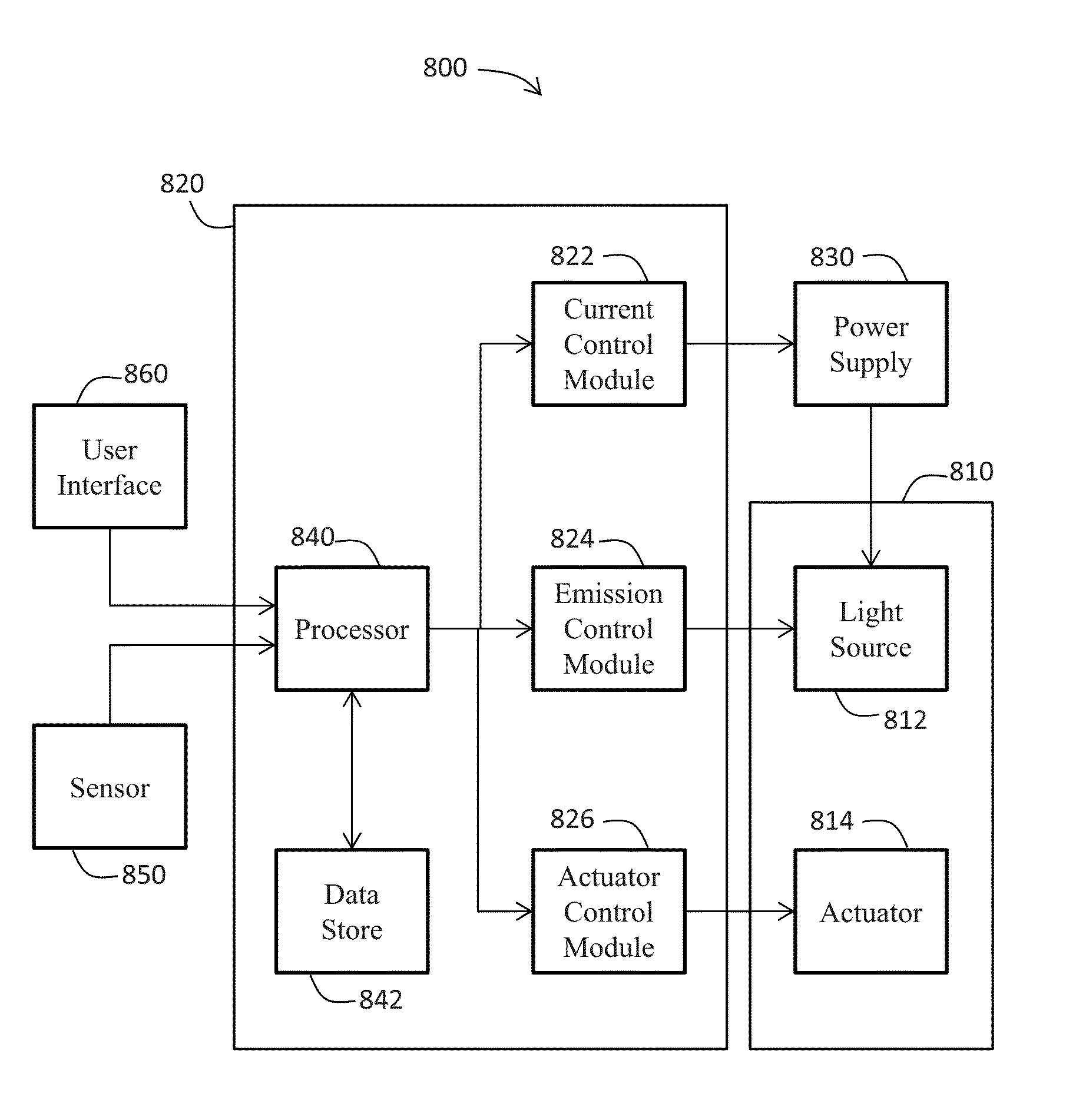
However, because each plant pigment absorbs light at one or more specific wavelengths, and the areas of peak absorption for each pigment are narrow, selecting and generating light wavelengths that produce superior plant growth remains a design challenge in grow light technology.
However, these conventional light sources suffer from various degrees of poor electrical efficiency (ranging from 10% to 40% of electrical energy consumed being converted to optical energy emitted within the visible spectral region) and low operation lifetimes (ranging from 1,000 hours to 24,000 hours of performance).
Furthermore, these conventional light sources cannot control the spectral quality of emissions without the inefficient and limited utilization of additional filters.
Moreover, these technologies' control of the radiation quantity is also limited, reducing the possibility of versatile lighting regimes such as pulsed operation.
Also, the red-blue light of conventional plant grow lights i

Method used


Image

  • Illumination and grow light system and associated methods
  • Illumination and grow light system and associated methods
  • Illumination and grow light system and associated methods

Examples


Example

[0043]The present invention will now be described more fully hereinafter with reference to the accompanying drawings, in which preferred embodiments of the invention are shown. This invention may, however, be embodied in many different forms and should not be construed as limited to the embodiments set forth herein. Rather, these embodiments are provided so that this disclosure will be thorough and complete, and will fully convey the scope of the invention to those skilled in the art. Those of ordinary skill in the art realize that the following descriptions of the embodiments of the present invention are illustrative and are not intended to be limiting in any way. Other embodiments of the present invention will readily suggest themselves to such skilled persons having the benefit of this disclosure. Like numbers refer to like elements throughout.

[0044]Although the following detailed description contains many specifics for the purposes of illustration, anyone of ordinary skill in th...


PUM


Abstract

A lighting system with selectable emission characteristics may include a housing, a controller, a first plurality of light sources operatively coupled to the controller and carried by the housing, and a second plurality of light sources operatively coupled to and controlled by the controller and carried by the housing. The first and second pluralities of light sources may be operable to emit first and second combined lights, respectively, and to emit a first light having a wavelength within the range of 650 nanometers to 700 nanometers, a second light having a wavelength within the range of 500 nanometers to 570 nanometers, and a third light having a wavelength within the range of 430 nanometers to 470 nanometer. The second light may be characterized by a human photopic response of greater than 0.0 and less than 0.4 throughout the range from 500 nanometers to 570 nanometers.

Description

RELATED APPLICATIONS[0001]This application is a continuation-in-part of and claims the benefit under 35 U.S.C. §119(e) of U.S. patent application Ser. No. 13 / 681,522 titled “Illumination and Grow Light System and Associated Methods” filed Nov. 20, 2012 (Attorney Docket No. 588.00001), which in turn claims the benefit of U.S. Provisional Patent Application No. 61 / 566,163 entitled “Plant Grow Light” filed Dec. 2, 2011, now expired, the entire contents of each of which are incorporated herein by reference, except to the extent disclosure therein is inconsistent with disclosure herein. This application is related to U.S. patent application Ser. No. 12 / 673,522 entitled “LED Lighting Device for Growing Plants” filed Aug. 15, 2008, now abandoned, and to U.S. patent application Ser. No. 10 / 468,155 entitled “Method of Cultivating Plants” filed Jan. 9, 2004, now abandoned, the entire contents of each of which are incorporated herein by reference, except to the extent disclosure therein is inc...

Claims


Application Information

Patent Timeline
IPC IPC(8): H05B37/02A01G7/04H05B44/00
CPCH05B37/0209A01G7/045H05B37/0227H05B45/22H05B45/20Y02P60/14
Inventor MAXIK, FREDRIC S.SOLER, ROBERT R.BARTINE, DAVID E.GROVE, ELIZA KATARYORIO, NEILCRAWFORD, ANTHONY
Owner BIOLOGICAL ILLUMINATION
Why Eureka
Try Eureka