Electronic substrate with heat dissipation structure

a technology of electronic substrate and heat dissipation structure, which is applied in the direction of electrical apparatus construction details, instruments, digital data processing details, etc., can solve the problems of poor heat dissipation efficiency of conventional hand-held electronic devices, large amount of heat produced by electronic elements in hand-held electronic devices, and poor heat dissipation efficiency of conventional heat-transfer plates designed for hand-held electronic devices. , to achieve the effect of improving heat dissipation efficiency,

Active Publication Date: 2016-01-07
ASIA VITAL COMPONENTS SHENZHEN CO LTD
View PDF2 Cites 22 Cited by
  • Summary
  • Abstract
  • Description
  • Claims
  • Application Information

AI Technical Summary

Benefits of technology

[0007]A further object of the present invention is to provide an electronic substrate with heat dissipation structure, which effectively prevents heat produced by a heat-producing element mounted thereon from accumulating in areas surrounding the heat-producing element, enabling the heat-producing element to operate at high efficiency and have extended service life.
[0008]To achieve the above and other objects, the electronic substrate with heat dissipation structure according to a preferred embodiment of the present invention includes a substrate plate and at least one heat pipe. The substrate plate includes a wiring layer, a grounding layer and an insulation layer. The wiring layer has a first side surface and an opposite second side surface, and is provided with a receiving hole. The first side surface has at least one heat-producing element mounted thereon. The receiving hole provided on the wiring layer is extended from a position in the vicinity of the heat-producing element to another position distant from the heat-producing element while penetrating the first and the second side surface of the wiring layer. The grounding layer has an upper side facing toward the wiring layer and attached to the second side surface, and a lower side facing away from the wiring layer. The insulation layer has an upper side facing toward and attached to the lower side of the grounding layer, and a lower side facing away from the grounding layer. The heat pipe is tightly fitted in the receiving hole with a lower surface of the heat pipe in full contact with the upper side of the grounding layer. The heat pipe includes a heat-absorption section and a heat-transfer section extended from the heat-absorption section; the heat-absorption section is fitted in a portion of the receiving hole located adjacent to the heat-producing element, and the heat-transfer section is fitted in another portion of the receiving hole located distant from the heat-producing element. With these arrangements, heat produced by the heat-producing element does not accumulate on areas of the substrat

Problems solved by technology

As a result of the constant progress in the electronic technological fields and the demands of users on the compact design and high operating performance of hand-held electronic devices, such as mobile phones, tablet computers, personal digital assistants (PDAs) and so on, electronic elements in the hand-held electronic devices, such as the central

Method used


Image

  • Electronic substrate with heat dissipation structure
  • Electronic substrate with heat dissipation structure
  • Electronic substrate with heat dissipation structure

Examples


Embodiment Construction

[0020]The present invention will now be described with some preferred embodiments thereof and with reference to the accompanying drawings. For the purpose of easy to understand, elements that are the same in the preferred embodiments are denoted by the same reference numerals.

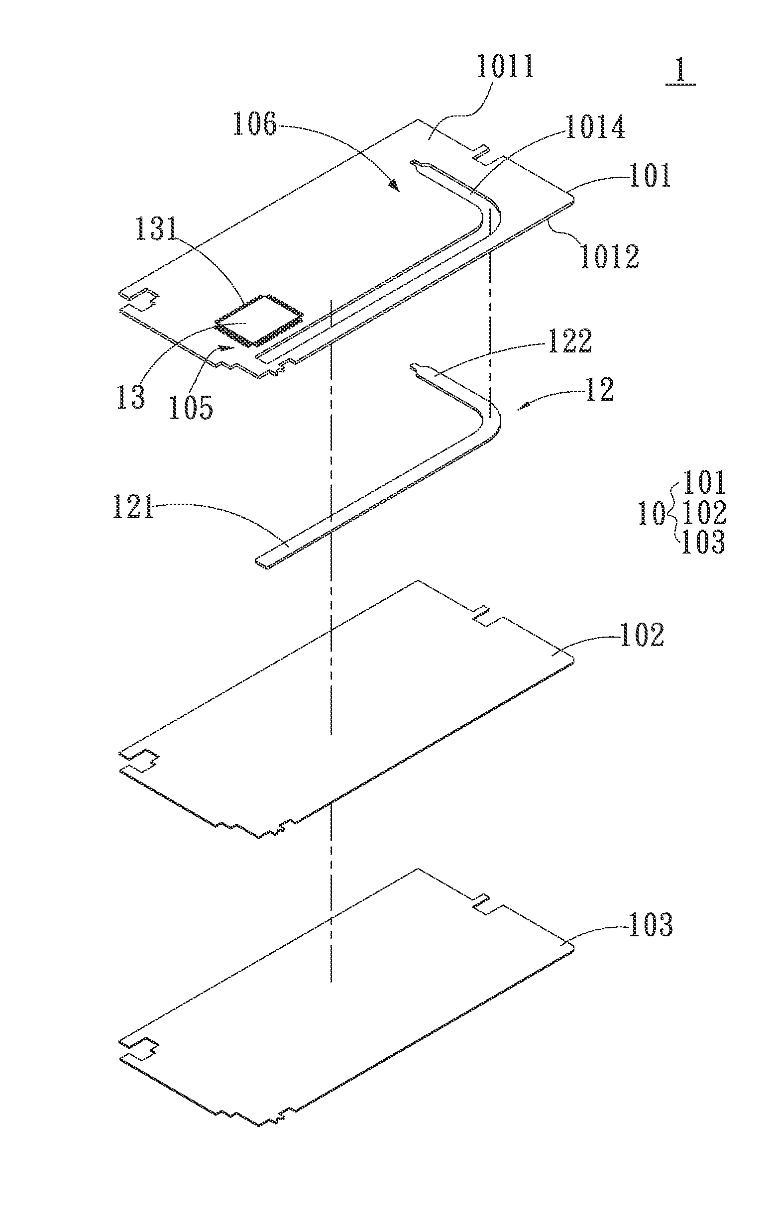
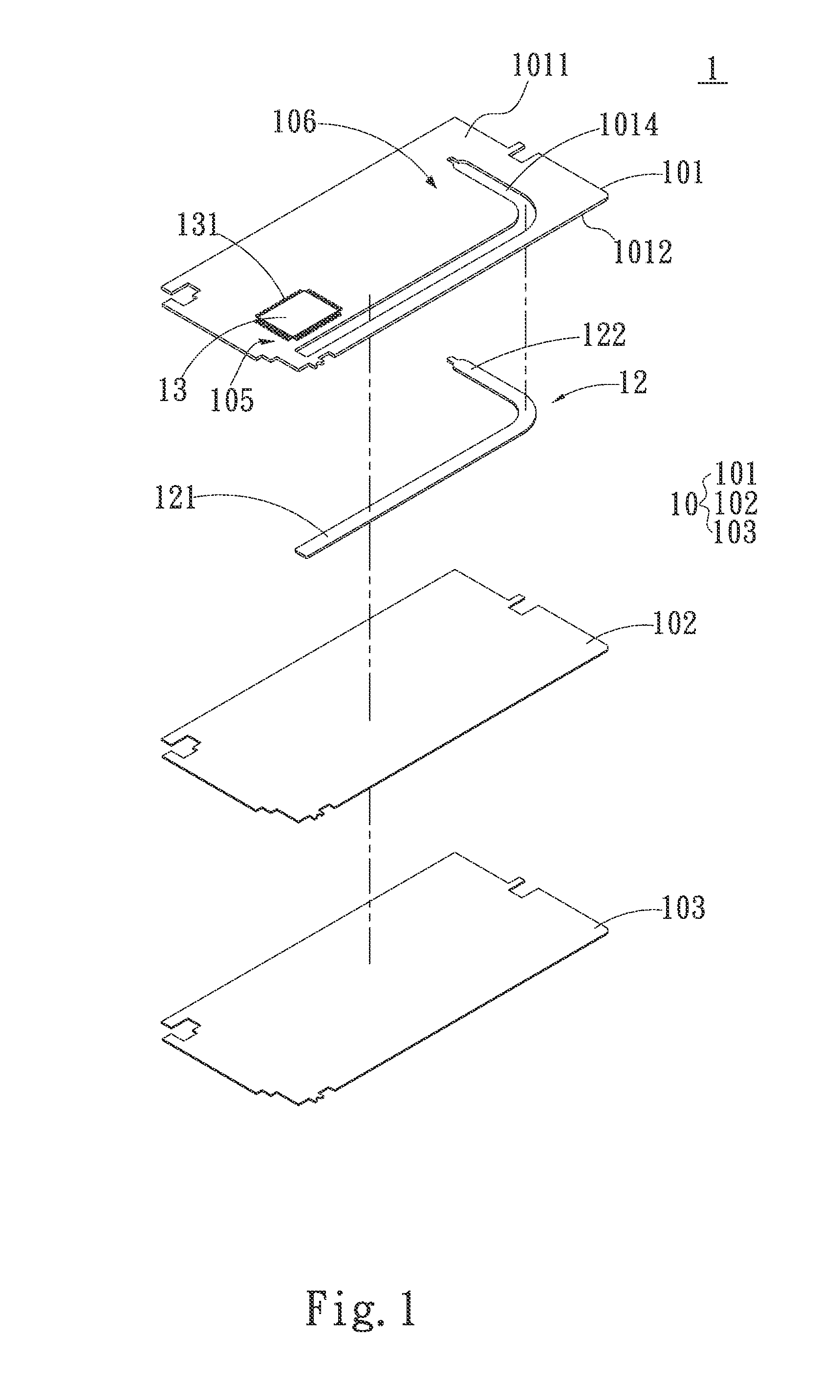
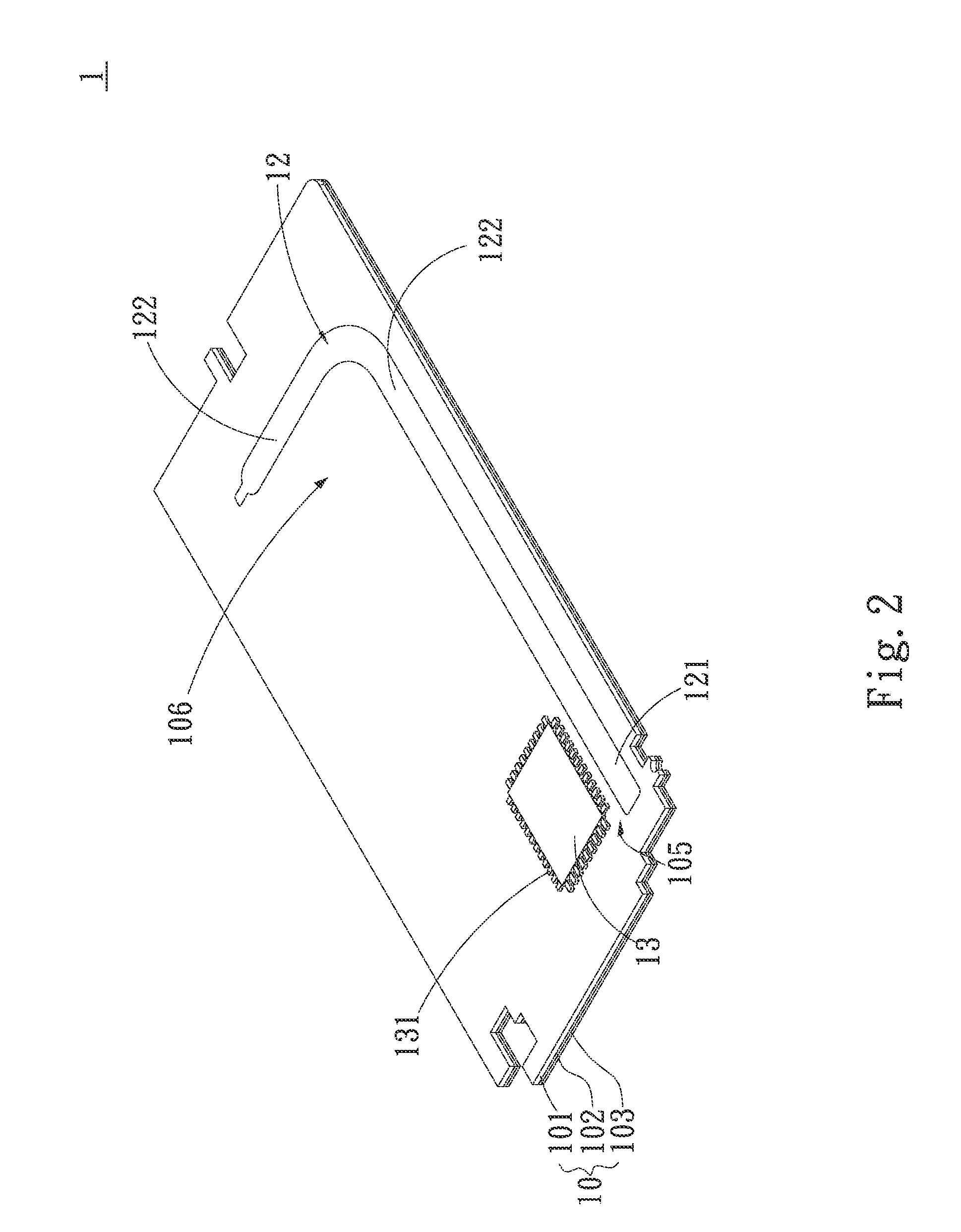
[0021]Please refer to FIG. 1 that is an exploded perspective view of an electronic substrate with heat dissipation structure according to a first preferred embodiment of the present invention, and to FIGS. 2 and 3 that are assembled perspective and sectional views, respectively, of the first preferred embodiment. For the purpose of conciseness, the electronic substrate with heat dissipation structure according to the present invention is also briefly referred to as the electronic substrate herein and generally denoted by reference numeral 1. As shown, the electronic substrate 1 includes a substrate plate 10 and at least one heat pipe 12. In the present invention, the substrate plate 10 includes, but not limited...


PUM


Abstract

An electronic substrate with heat dissipation structure includes a substrate plate and at least one heat pipe. The substrate plate includes a wiring layer, a grounding layer and an insulation layer from top to bottom. The wiring layer has at least one heat-producing element mounted thereon, and is formed with a receiving hole for the heat pipe to tightly fit therein. Heat produced by the heat-producing element and distributed over a high-temperature zone of the substrate plate surrounding the heat-producing element is absorbed by the heat pipe and then transferred to a low-temperature zone of the substrate plate distant from the heat-producing element, from where the heat is dissipated into ambient air to achieve cooling effect at upgraded heat dissipation efficiency.

Description

FIELD OF THE INVENTION[0001]The present invention relates to an electronic substrate, and more particularly to an electronic substrate that is provided with a heat dissipation structure to enable upgraded heat dissipation efficiency without increasing an overall thickness of the electronic substrate.BACKGROUND OF THE INVENTION[0002]As a result of the constant progress in the electronic technological fields and the demands of users on the compact design and high operating performance of hand-held electronic devices, such as mobile phones, tablet computers, personal digital assistants (PDAs) and so on, electronic elements in the hand-held electronic devices, such as the central processing unit (CPU) and integrated circuits (ICs), produce a large amount of heat during high-speed operation thereof. The produced heat tends to accumulate in the very limited internal space of the compact electronic devices, and must be timely removed to ensure good operating efficiency and extended service...

Claims


Application Information

Patent Timeline
IPC IPC(8): H05K7/20G06F1/20
CPCG06F1/203H05K7/20336H05K1/0203H05K1/0272
Inventor WU, CHUN-MING
Owner ASIA VITAL COMPONENTS SHENZHEN CO LTD
Why Eureka
Try Eureka