Capacitive micromachined ultrasonic transducer probe using wire-bonding
- Summary
- Abstract
- Description
- Claims
- Application Information
AI Technical Summary
Benefits of technology
Problems solved by technology
Method used
Image

Examples
Embodiment Construction
[0027]Reference will now be made in detail to exemplary embodiments, examples of which are illustrated in the accompanying drawings. In the drawings, the thicknesses of layers and regions are exaggerated for clarity. The present inventive concept may, however, be embodied in many different forms, and should not construed as limited to the exemplary embodiments set forth herein. It will also be understood that when an element is referred to as being “above’ or “on” another element, it can be directly on the other element, or intervening layers may also be present. Like reference numerals in the drawings denote like elements throughout the specification, and thus their description will be omitted.
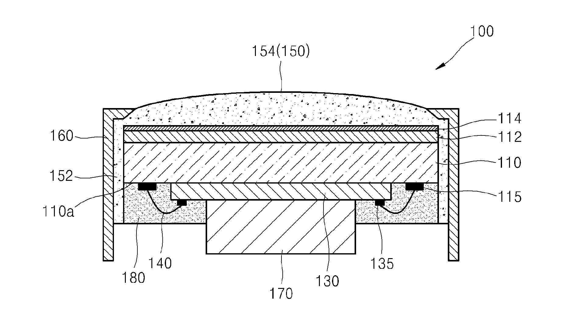
[0028]FIG. 1 is a schematic cross-sectional view of the structure of a capacitive micromachined ultrasonic transducer (CMUT) probe 100, according to one or more exemplary embodiments.
[0029]Referring to FIG. 1, the CMUT probe 100 includes a CMUT chip 110 and a printed circuit board (PCB) 130. ...
PUM
 Abstract
Description
Claims
Application Information
 - R&D
- Intellectual Property
- Life Sciences
- Materials
- Tech Scout
- Unparalleled Data Quality
- Higher Quality Content
- 60% Fewer Hallucinations
Browse by: Latest US Patents, China's latest patents, Technical Efficacy Thesaurus, Application Domain, Technology Topic, Popular Technical Reports.
© 2025 PatSnap. All rights reserved.Legal|Privacy policy|Modern Slavery Act Transparency Statement|Sitemap|About US| Contact US: help@patsnap.com