Inflatable Medical Compression Device

a compression device and inflatable technology, applied in the field of compression device and inflammation care, can solve the problems of high cost, difficult use either by the individual user or outside of a hospital or clinical setting, and existing military or emergency care methods to control bleeding caused by traumatic injuries have serious drawbacks to cost, efficiency, effectiveness, design & operation, and patient safety concerns. , to achieve the effect of less costly manufacture and user friendly

Inactive Publication Date: 2016-01-14
ELLIOT JERRY C
View PDF4 Cites 11 Cited by
  • Summary
  • Abstract
  • Description
  • Claims
  • Application Information

AI Technical Summary

Benefits of technology

[0013]Whereas previous and current compression bladders are / were cumbersome, potentially dangerous if used on the patient improperly, not user friendly, required to be installed with patient assistance, are not suitable for home or non-hospital use in a therapeutic. setting and expensive, the present invention is portable, less costly to manufacture, can be installed on the patient without requiring patient transport, is very user friendly, and can be installed and used by the patient without assistance.

Problems solved by technology

These are typically expensive and difficult to use either by the individual user or outside of a hospital or clinical setting.
Similarly, existing military or emergency care methods to control bleeding caused by traumatic injury have serious drawbacks to cost, efficiency, effectiveness, design & operation and particularly patient safety concerns.
There is some controversy over use of MAST.
Another reason they have fallen into disuse is the tendency for emergency room nurses and physicians to cut the inflated trousers off, which can cause a catastrophic drop in blood pressure, as well as equipment destruction and an increased strain on budgets.
While the PASG and MASTs can be useful adjuncts in the treatment of hemorrhagic shock in certain circumstances, either device can worsen the problem in others.

Method used


Image

  • Inflatable Medical Compression Device
  • Inflatable Medical Compression Device
  • Inflatable Medical Compression Device

Examples


Embodiment Construction

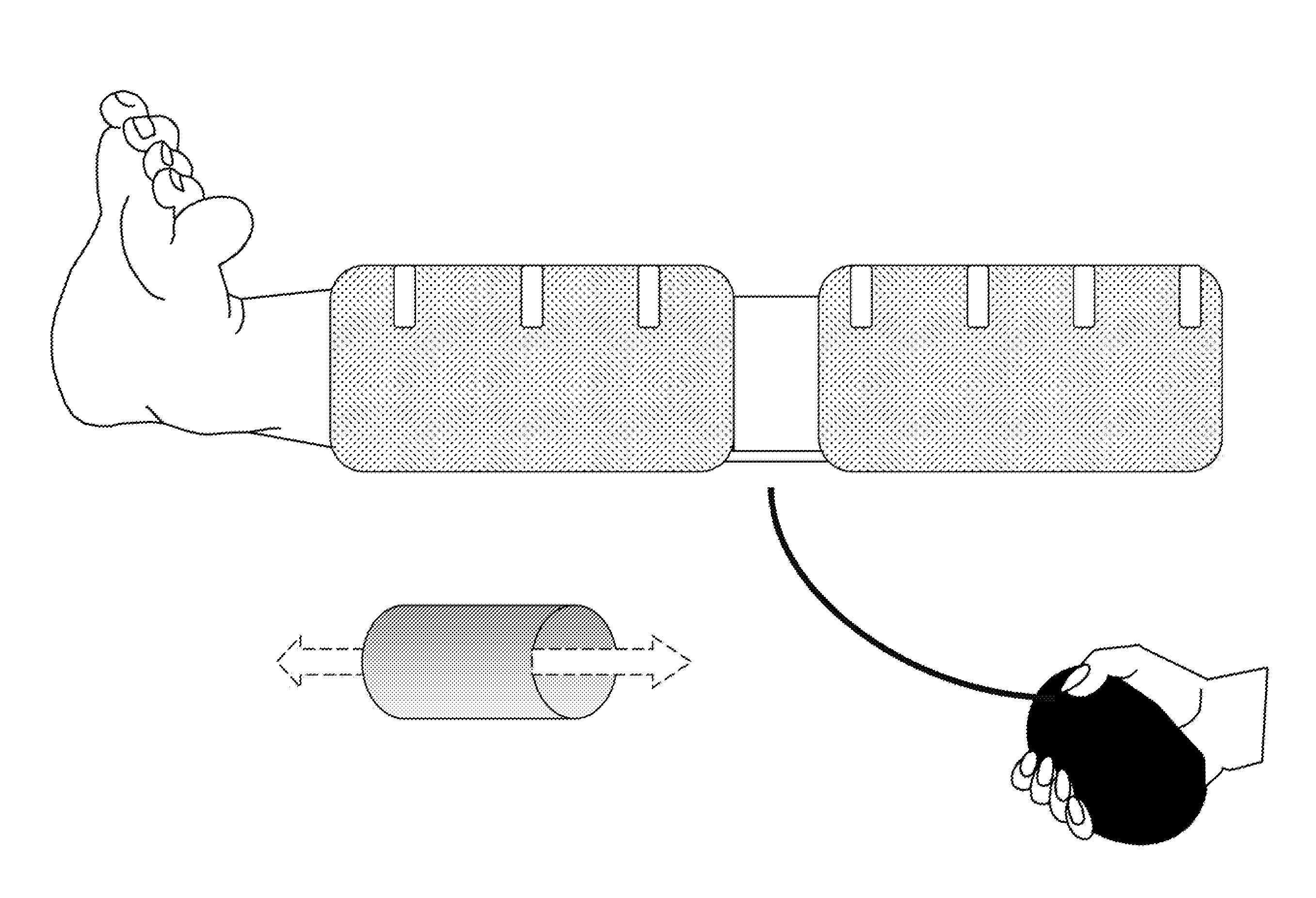
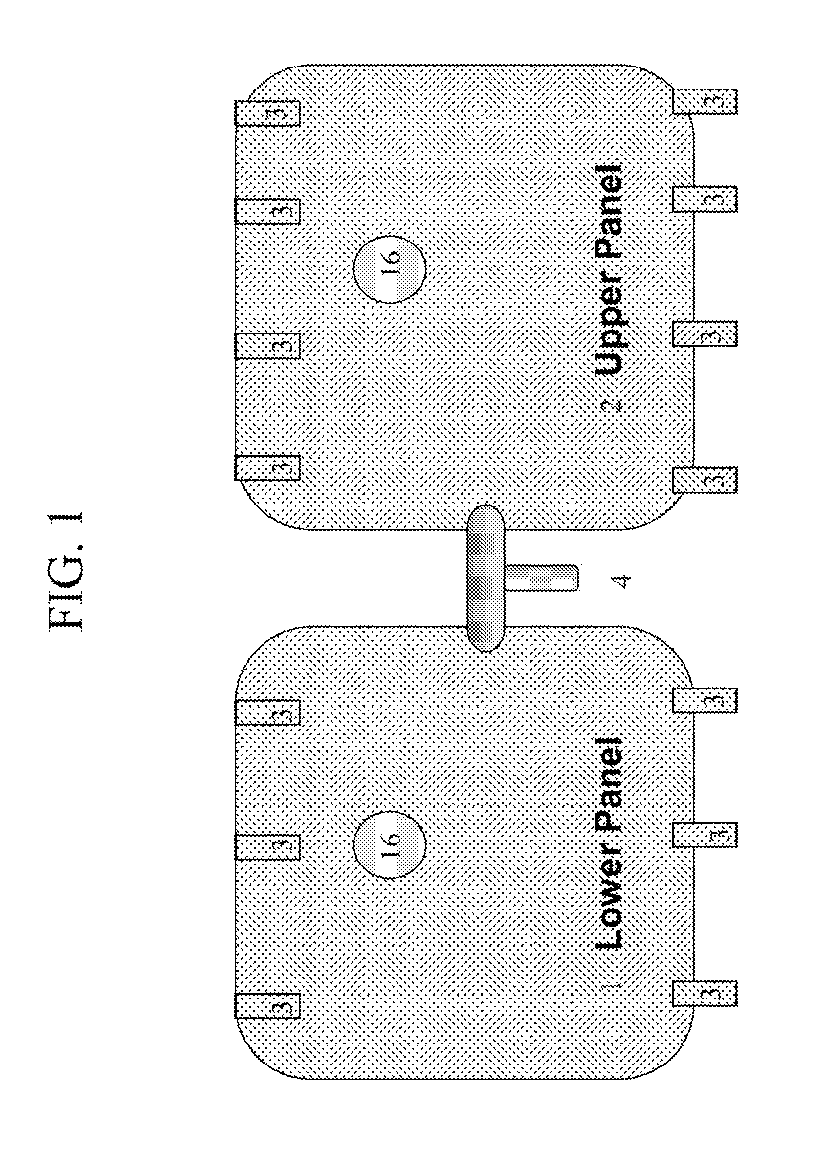
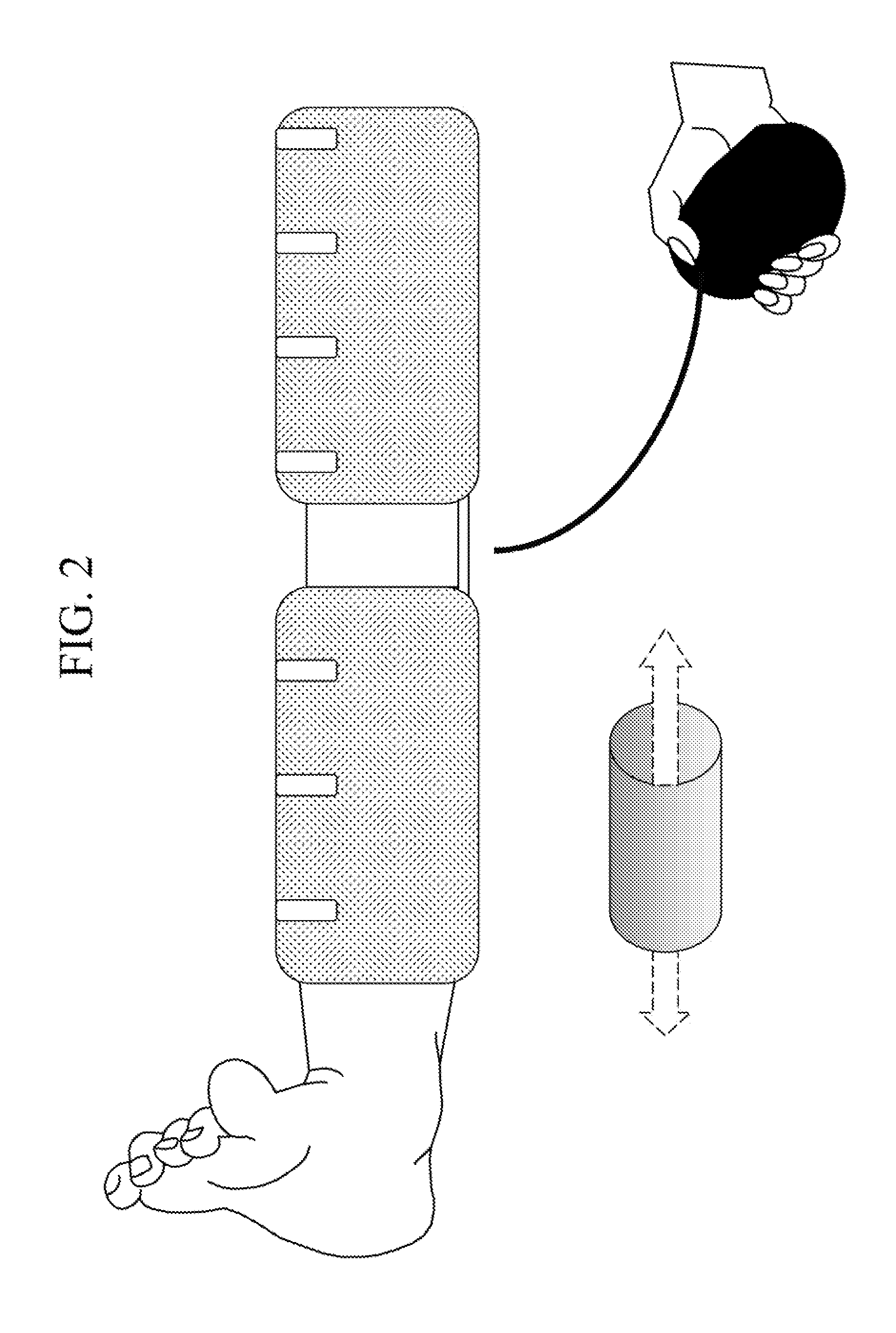
[0018]Referring to FIG. 1, an anti-blood pooling device for the treatment of blood flow issues is depicted. The device is used to compress a limb of a human. In an exemplary embodiment, the invention is comprised of a lower bladder 1, an upper bladder 2 and a plurality of hook and loop fasteners 3 suitably placed to allow compressive closure of each of the bladders 1 and 2 over the limb of a patient. Bladders 1 and 2 may be made of any suitable material. In the exemplary embodiment, one bladder 1 or 2 is suitable for use on one end of a joint of a limb, such as a knee or elbow, with the other bladder 1 or 2 is placed on the other side of the joint. For example, in a typical use, bladder 1 may be placed on a leg calf and bladder 2 may be placed on the thigh.

[0019]Bladder 1 and bladder 2 are fixedly or removeable and also flexibly connected by a t-valve 4 allowing simultaneous inflation of bladders 1 and 2. As further shown in FIG. 1, during use, bladder 1 may be secured around the lo...


PUM


Abstract

The disclosed invention aids the treatment of vascular problems with blood circulation in the body extremities by mechanically increasing or assisting the venous blood flow and prevents or minimizes shock through the application of controlled external pressure. In an alternate use, the device can also he used to compress a limb wound to reduce loss of blood in accidents and injuries during military operations. The invention comprises of two inflatable air bladders with a switchable filling valve to enable inflation of both bladders simultaneously or separately. The invention is inflated by either air or liquids for compression, fillable by mouth or hand pump, with the level of compression controllable by the user or installer. The invention is of reduced weight, allows as of manufacture and is of low cost. The invention is highly portable arid storable for battlefield or ambulance emergency care uses, flexible, easily and quickly installed.

Description

BACKGROUND OF THE INVENTION[0001]The invention relates generally to compression device and inflammation care, treatment of trauma, bleeding and other medical conditions requiring or aided by a controlled general pressure applied to a limb for which control of bleeding or blood circulation is indicated. The invention is also generally useful for the prevention or minimization of deep vein thrombosis and varicose veins in elderly, wheelchair and bed-confined patients who are non-ambulatory.[0002]The current method of treating vascular problems has been to slip the limb, typically the leg, into an elastic type stocking or rubberized trousers. These are typically expensive and difficult to use either by the individual user or outside of a hospital or clinical setting. Similarly, existing military or emergency care methods to control bleeding caused by traumatic injury have serious drawbacks to cost, efficiency, effectiveness, design & operation and particularly patient safety concerns. ...

Claims


Application Information

Patent Timeline
Patent Type & Authority Applications(United States)
IPC IPC(8): A61H1/00
CPCA61H2201/0103A61H1/008A61B17/135
Inventor ELLIOT, JERRY, C
Owner ELLIOT JERRY C
Why Eureka
Try Eureka