Inspection system for inspecting object using force sensor

Inactive Publication Date: 2016-01-14
FANUC LTD
View PDF3 Cites 3 Cited by
  • Summary
  • Abstract
  • Description
  • Claims
  • Application Information

AI Technical Summary

Benefits of technology

[0016]According to a tenth aspect, in the inspection system according to the ninth aspect, the quality determination part is configured to determine that the object has a good quality in the case where, when the inspection gauge and the machined portion are fitted to each other, the second inspection portion of the inspection gauge can be fitted to the machined portion and the first inspection portion of the inspection gauge cannot be fitted to the machined portion, and determine that the object has a

Problems solved by technology

If the alignment is not accurate, the inspection gauge and the object may interfere with each other and cannot fit each other

Method used


Image

  • Inspection system for inspecting object using force sensor
  • Inspection system for inspecting object using force sensor
  • Inspection system for inspecting object using force sensor

Examples


Example

[0034]Embodiments of the present invention will be described with reference to the accompanying drawings. The illustrated constituent elements may be modified in size in relation to one another as necessary for better understanding of the present invention. The identical or corresponding constituent elements are designated with the same referential numerals.

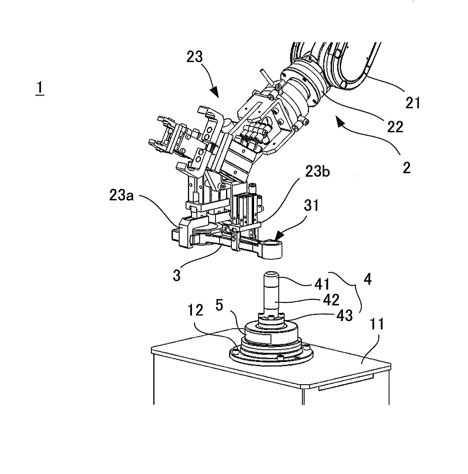
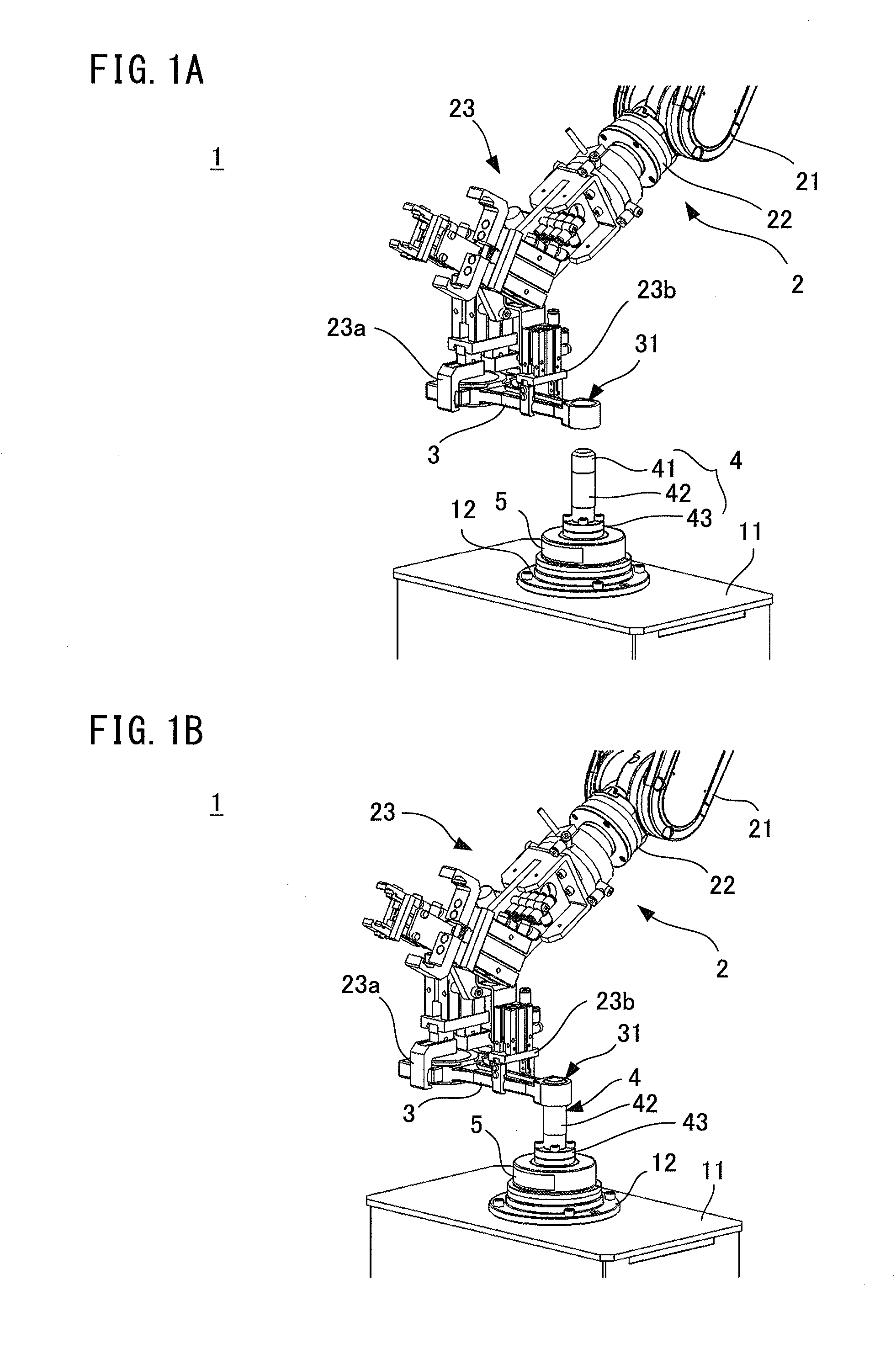
[0035]FIG. 1A is a perspective view illustrating an exemplary configuration of an inspection system 1 according to one embodiment. The inspection system 1 includes a multiple joint robot (hereinafter simply referred to as “the robot”) 2 having a plurality of joints, each of which is driven by a servo motor. In FIG. 1A, only part of the robot 2 is illustrated, including an arm 21, and a wrist 22 attached to a tip of the arm 21. The wrist 22 is provided with a hand 23 which includes a pair of chucks 23a and 23b for releasably holding an inspection object (hereinafter simply referred to as “the object”) 3. The object 3 is formed wit...


PUM


Abstract

An inspection system includes a force sensor for detecting force acting between an inspection gauge and an object formed with a machined portion. The inspection system determines the quality of the machined portion, based on a positional relationship between the object and the inspection gauge when the inspection gauge and the machined portion are fitted to each other. The fitting operation between the inspection gauge and the machined portion is carried out by a robot which is operated in accordance with force control using a detection value of the force sensor.

Description

BACKGROUND ART[0001]1. Technical Field[0002]The present invention relates to an inspection system for inspecting the accuracy of the size of an object.[0003]2. Description of the Related Art[0004]A known inspection system inspects the accuracy of the size of a machined hole by moving a movable body which supports an inspection gauge sized based on the allowable size of the machined hole, toward the machined hole, so as to insert the inspection gauge into the machined hole (see JP 2002-195803 A and JP 2012-103081 A). Another known inspection system inspects the accuracy of the size of an outer diameter of a cylindrical article by moving the article through a hole having a predetermined size (see JP 2008-058069 A). As described above, it is known to inspect accuracy of the size of an object by fitting the object and the inspection gauge to each other.[0005]However, according to the above-described known technique, it is necessary to accurately align the object relative to the inspecti...

Claims


Application Information

Patent Timeline
IPC IPC(8): B25J9/16B25J19/02
CPCB25J9/1679Y10S901/09B25J19/02B25J9/1633B25J13/085G05B19/401G05B2219/37207G05B2219/37357G05B2219/40032
Inventor UEDA, TETSUJIODA, MASARU
Owner FANUC LTD
Why Eureka
Try Eureka