Apparatus, method, and system for diagnosing reductant delivery performance

a reductant and apparatus technology, applied in the field of apparatus, method and system for diagnosing the delivery performance of reductants, can solve the problems of reduced reductant flow rate, and inability to convert enough no/sub>x/sub> in the scr system, etc., to achieve the effect of reducing the reductant flow rate and reducing the flow ra

Active Publication Date: 2016-01-14
CUMMINS INTPROP INC
View PDF6 Cites 17 Cited by
  • Summary
  • Abstract
  • Description
  • Claims
  • Application Information

AI Technical Summary

Benefits of technology

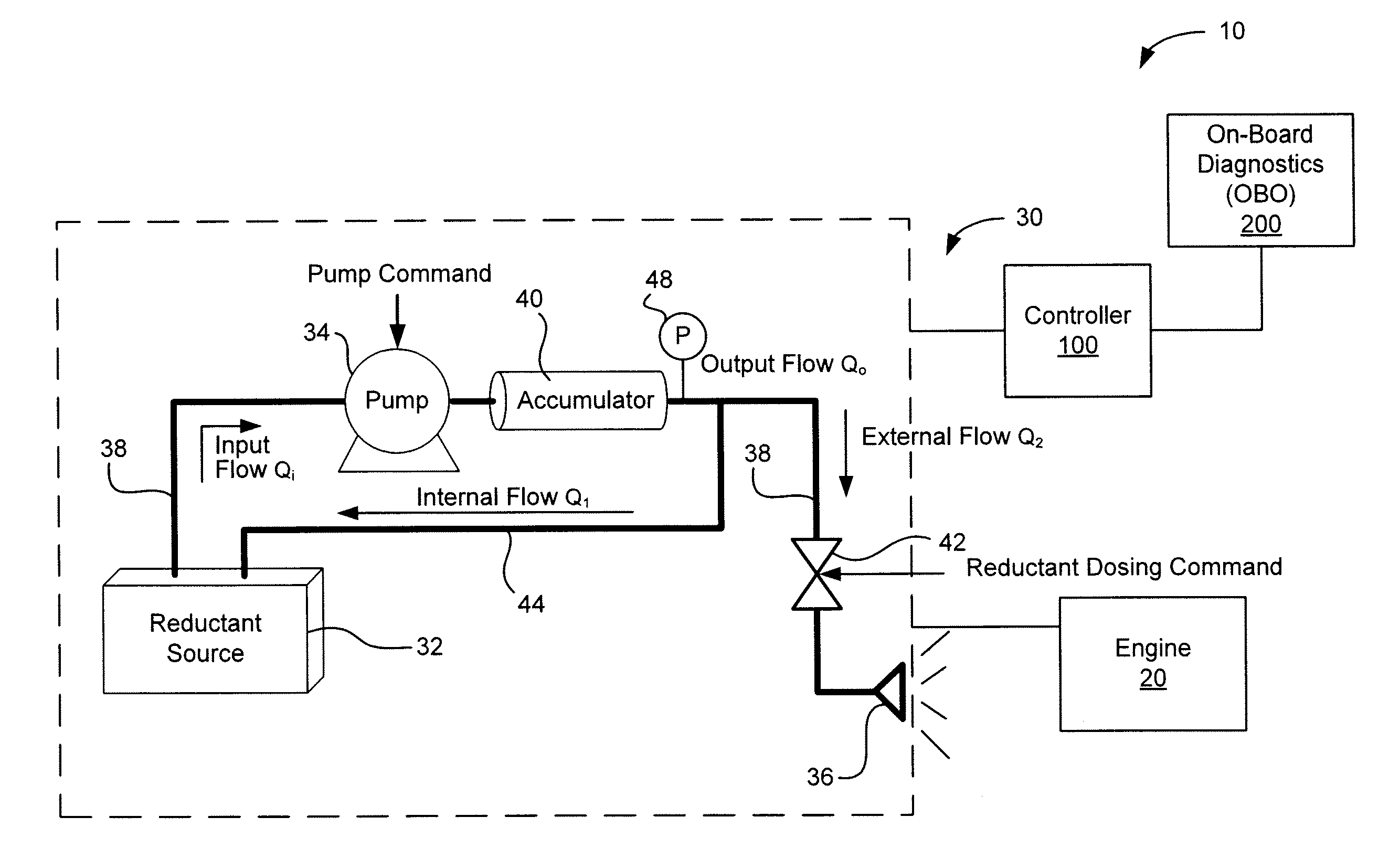
[0006]The subject matter of the present application has been developed in response to the present state of the art, and in particular, in response to the problems and needs in the art that have not yet been fully solved by currently available exhaust aftertreatment systems. Accordingly, the subject matter of the present application has been developed to provide apparatus, methods, and systems for diagnosing reductant delivery systems that overcomes at least some shortcomings of the prior art aftertreatment systems.
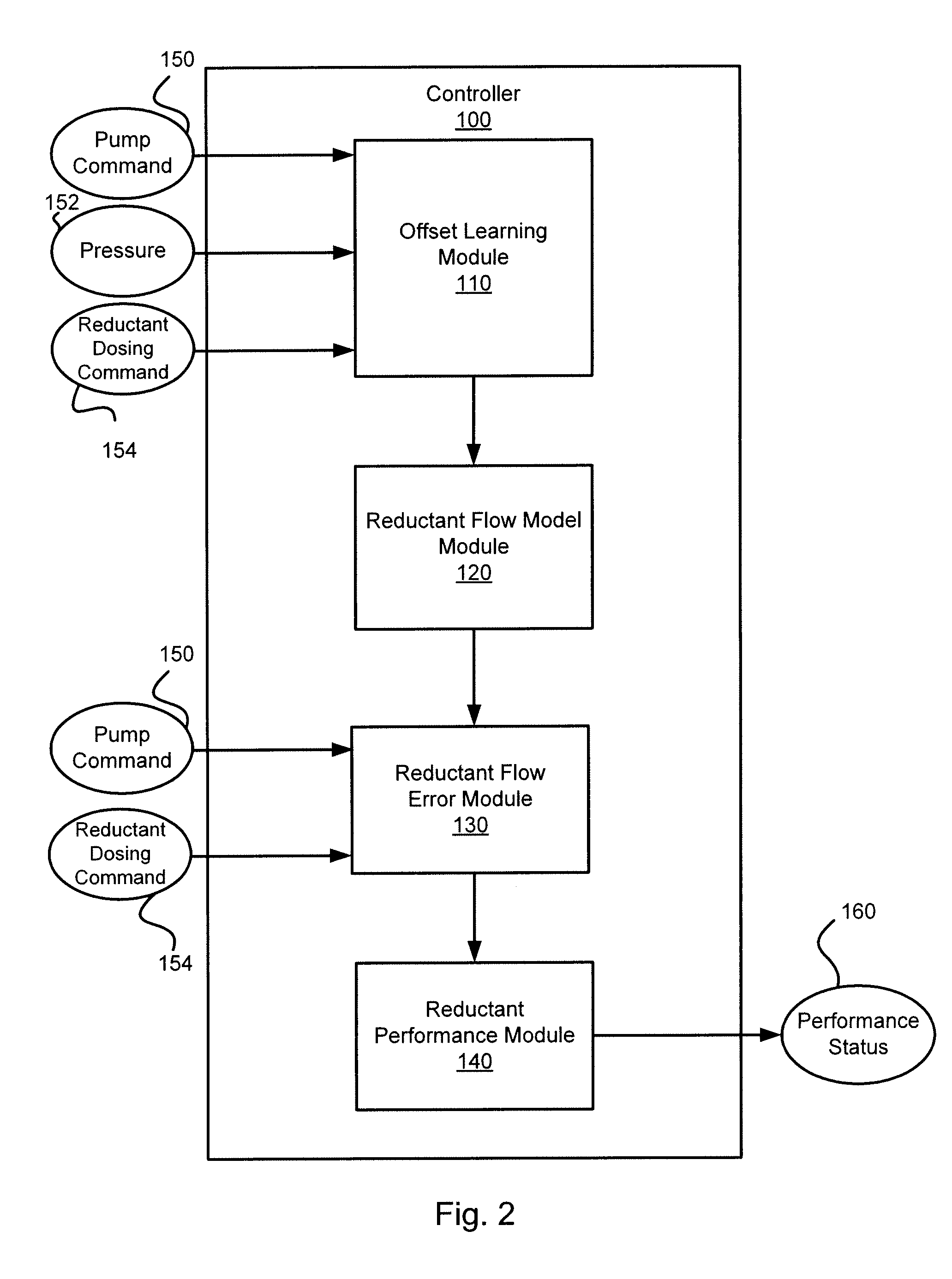
[0007]An implementation relates to a system comprising a reductant delivery system having a reductant pump and a controller. The controller may be configured to determine a flow rate offset value for the reductant delivery system. The flow rate offset value may be based on a first pump command value for the reductant pump when an output pressure value is stabilized and a first reductant dosing command value is zero. The controller may be further configured to determine a first reduced reductant flow rate for a second reductant dosing command value based, at least in part, on the determined flow rate offset when the second reductant dosing command is non-zero. The controller may still further be configured to determine a first reductant flow rate error based, at least in part, on a difference between a reductant flow rate value corresponding to the second reductant dosing command value and the first determined reduced reductant flow rate. The controller may also be configured to output a performance status value indicative of a performance status of the reductant delivery system based, at least in part, on the determined first reductant flow rate error and a predetermined threshold.
[0008]Another implementations relates to a non-transitory computer-readable medium storing one or more instructions that, when executed by one or more processors, cause the one or more processors to perform several operations. The operations may include determining a flow rate offset value for a reductant delivery system. The flow rate offset value may be based on a first pump command value for a reductant pump when an output pressure value is stabilized and a first reductant dosing command value is zero. The operations may also include determining a second pump command value for the reductant pump when the output pressure value is stabilized for a second reductant dosing command value when the second reductant dosing command value is non-zero. The operations may further include determining a first reduced reductant flow rate for the second reductant dosing command value based on the determined flow rate offset and the second pump command value. The operations may still further include determining a first reductant flow rate error based, at least in part, on a difference between a reductant flow rate value corresponding to the second reductant dosing command value and the first determined reduced reductant flow rate. The operations may yet further include outputting a performance status value indicative of a performance status of the reductant delivery system based, at least in part, on the determined first reductant flow rate error and a predetermined threshold.
[0009]Yet another implementation relates to a method for determining a performance status of a reductant delivery system having a reductant pump, a control valve, and a delivery mechanism. The method may include determining an internal flow rate offset value and determining a reductant flow rate model based on the determined internal flow rate offset value and a slope value. The reductant flow rate model may generate an expected reductant flow rate for a normal-operating reductant delivery system responsive to an inputted pump command value. The method may also include outputting a reductant dosing command value based on a desired reductant dosing flow rate to the control valve. The method may further include determining a pump command value for the reductant dosing command value and determining a reduced reductant flow rate based on the determined reductant flow rate model and the determined pump command value. The method may still further include determining a reductant flow rate error value based, at least in part, on a difference between the desired reductant dosing rate and the determined reduced reductant flow rate. The method may yet further include outputting a performance status value indicative of a performance of the reductant delivery system based on the reductant flow rate error value and a predetermined threshold value.

Problems solved by technology

However, currently available SCR systems also suffer from a few drawbacks.
However, if the reduction reaction rate is too slow, or if a deficient amount of reductant is introduced into the exhaust stream upstream of the SCR catalyst, the SCR system may be unable to convert enough NOx.
The reductant delivery system may under-deliver the needed amount of reductant due to blockage of the reductant flow within the system.
For example, there may be unintentional or intentional restrictions in the pressure line of the system.
One known indication of the inability of an SCR system to covert enough NO is the inability to deliver the necessary amount of reductant for NOx conversion due to blockage within the reductant delivery system.
Known systems and associated diagnostics fail to adequately diagnose poor performance of reductant delivery systems due to blockage or other failures, and thus may fail to provide the data to the OBD system or unit regarding the malfunction of reductant delivery systems.

Method used


Image

  • Apparatus, method, and system for diagnosing reductant delivery performance
  • Apparatus, method, and system for diagnosing reductant delivery performance
  • Apparatus, method, and system for diagnosing reductant delivery performance

Examples


Embodiment Construction

[0016]Reference throughout this specification to features, advantages, or similar language does not imply that all of the features and advantages that may be realized with the subject matter of the present disclosure should be or are in any single implementation. Rather, language referring to the features and advantages is understood to mean that a specific feature, advantage, or characteristic described in connection with an implementation is included in at least one implementation of the present disclosure. Thus, discussion of the features and advantages, and similar language, throughout this specification may, but do not necessarily, refer to the same implementation.

[0017]The described features, structures, advantages, and / or characteristics of the subject matter of the present disclosure may be combined in any suitable manner in one or more implementations. In the following description, numerous specific details are provided to impart a thorough understanding of implementations ...


PUM


Abstract

A system for diagnosing and/or determining the performance of a reductant delivery system may include determining a flow rate offset value for the reductant delivery system. A reduced reductant flow rate may be determined for a reductant dosing command value based, at least in part, on the determined flow rate offset when reductant dosing command is non-zero. A reductant flow rate error can be determined based, at least in part, on a difference between an expected reductant flow rate value corresponding to the reductant dosing command value and the determined reduced reductant flow rate. A performance status value indicative of a performance status of the reductant delivery system may be outputted based, at least in part, on the determined first reductant flow rate error and a predetermined threshold.

Description

CROSS-REFERENCE TO RELATED PATENT APPLICATIONS[0001]This application claims priority from U.S. Provisional Patent Application No. 61 / 770,179, entitled “Apparatus, Method and System for Diagnosing Reductant Delivery Performance,” and filed Feb. 27, 2013, the contents of which are hereby incorporated herein by reference in the entirety.BACKGROUND OF THE INVENTION[0002]Emissions systems for compression-ignition (e.g., diesel) engines typically monitor the release of carbon monoxide (CO), unburned hydrocarbons (UHC), diesel particulate matter (PM) such as ash and soot, and nitrogen oxides (NOx).[0003]With regard to reducing NO emissions, NO reduction catalysts, including selective catalytic reduction (SCR) systems, are utilized to convert NOx (NO and NO2 in some fraction) to N2 and other compounds. SCR systems utilize a reductant, typically ammonia, to reduce the NOx. Currently available SCR systems can produce high NOx conversion rates allowing the combustion technologies to focus on p...

Claims


Application Information

Patent Timeline
Patent Type & Authority Applications(United States)
IPC IPC(8): F01N3/20F01N11/00
CPCF01N3/208F01N2610/144F01N11/00F01N2550/05F01N2610/02F01N2610/146F01N2900/1812F01N2900/1821F01N2900/1822F17D3/00Y02T10/12Y02T10/40
Inventor WANG, KERANGMCDANIEL, MICKEY R.YUAN, YISINGH, BALBAHADUR
Owner CUMMINS INTPROP INC
Why Eureka
Try Eureka