
Pressure Profiling System

a profiling system and pressure technology, applied in the field ofpressure profiling, can solve the problems of complex tubes, pressure registration components, and other data-acquisition devices, and achieve the effects of reducing the number of potential failure points

Active Publication Date: 2016-01-14
INT ELECTRONICS MACHINES
View PDF7 Cites 22 Cited by
  • Summary
  • Abstract
  • Description
  • Claims
  • Application Information

AI Technical Summary

Benefits of technology

The patent describes a solution for obtaining pressure and other information from the flow of air over airfoils and other surfaces. The solution includes a pressure sensor nodes that are affixed to the object and have a set of pressure sensors and a processing component. The processing component receives data from the pressure sensors and communicates it to a computer system using a wireless communications component. The technical effect of this approach is that it provides a more effective way of obtaining pressure data for objects, allowing for better detection and analysis of airflow patterns.

Problems solved by technology

The tubes, pressure registration components, and other data-acquisition devices are complex, weighty, and require clear space for routing them through the airfoil.
Moreover, such runs of tubing and connections have a myriad of potential failure points, including pinched tubes, holes, seal leaks, faulty electrical connections, etc.
Installation of such a pressure-measurement system also can require a significant amount of labor.
As a result, for pressure profiling a model of a commercial aircraft, for example, the cost for the test can exceed half a million dollars for this portion of the work alone.
These films provide qualitative data, but cannot provide accurate quantitative data as to the pressure distribution and behavior.
Additionally, a responsiveness of the films is limited, and permanent data acquisition using the films is challenging to implement.
As with previous approaches, this approach proposes placement of a millimeter-scale object in the airflow, and utilizes multiple tubes, each of which presents a potential point of failure or mis-manufacture.
These pressure belts can provide reasonable performance, but require wired power and data connections, each of which provides an additional point of failure and requires direct modification of the airfoil.

Method used


Image

  • Pressure Profiling System
  • Pressure Profiling System
  • Pressure Profiling System

Examples


Embodiment Construction

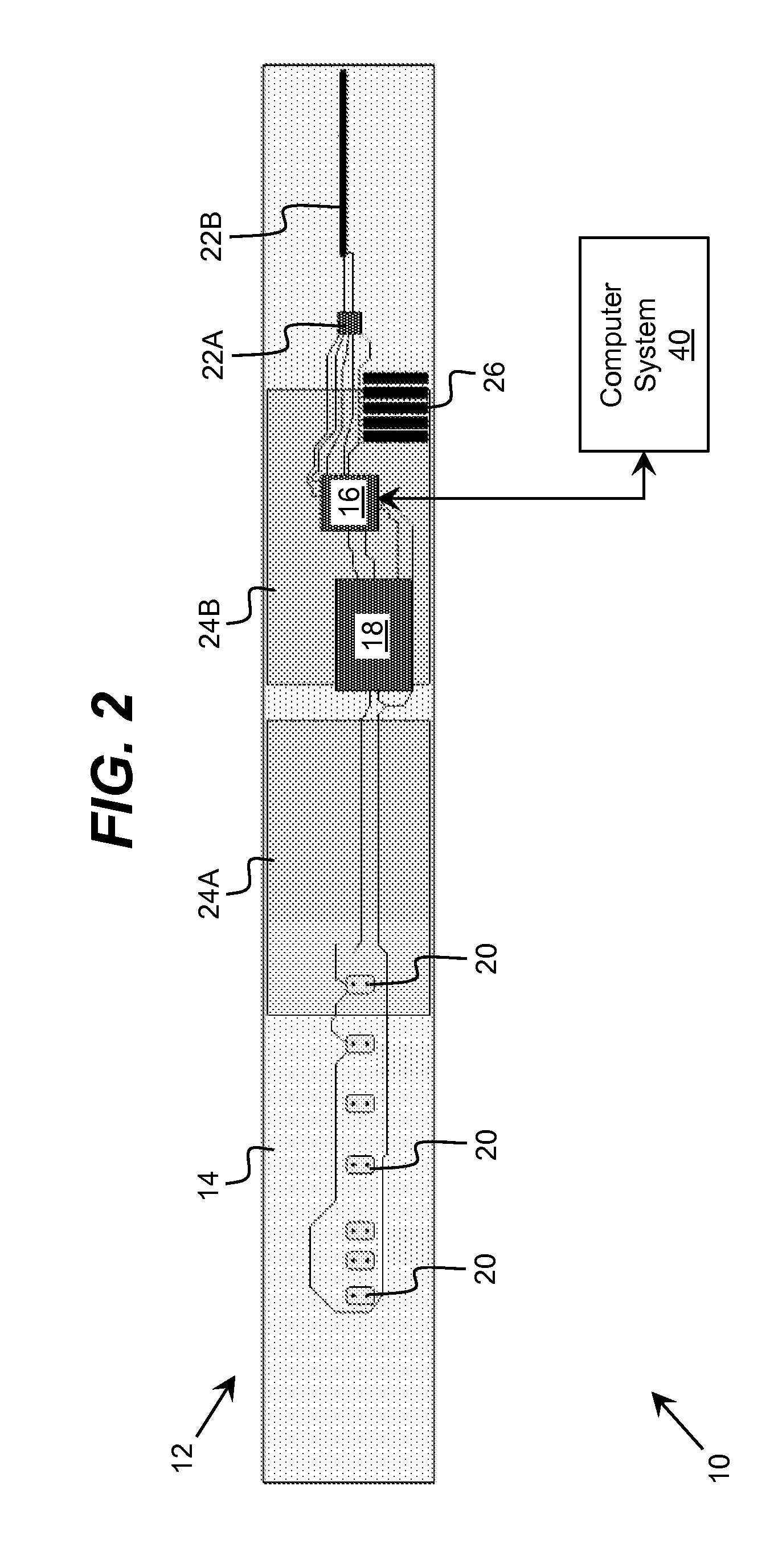
[0021]As indicated above, aspects of the invention provide a solution for acquiring pressure data for an object, such as an airfoil. One or more pressure sensor nodes are utilized, each of which includes a set of pressure sensors and a processing component. The pressure sensor node(s) are affixed to the object in a manner that enables the pressure sensors to acquire pressure data for a set of locations on the surface of the object. A pressure sensor node also can include a wireless communications component to provide wireless communications between the pressure sensor node and a computer system. As used herein, unless otherwise noted, the term “set” means one or more (i.e., at least one) and the phrase “any solution” means any now known or later developed solution.

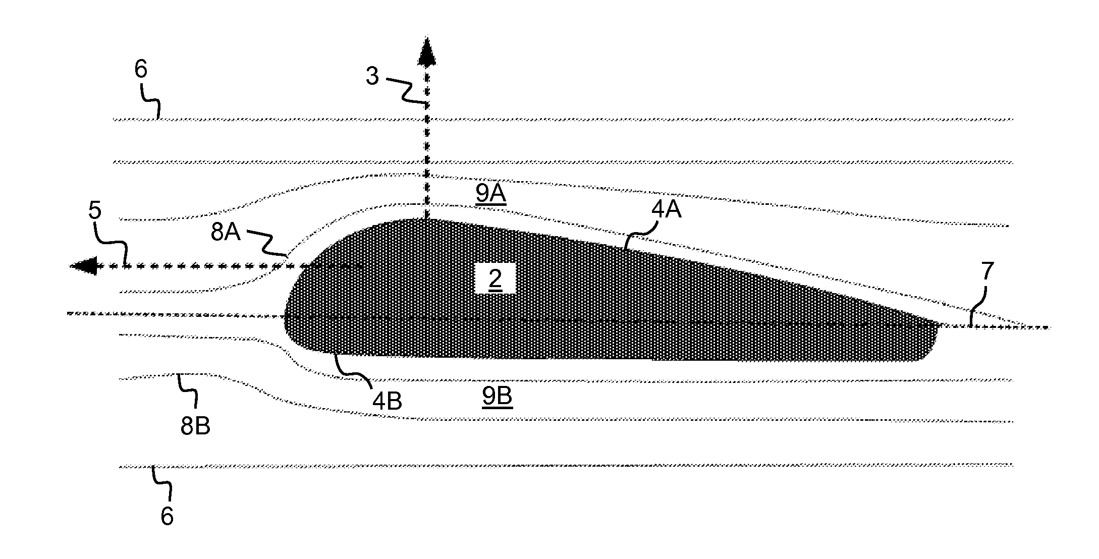
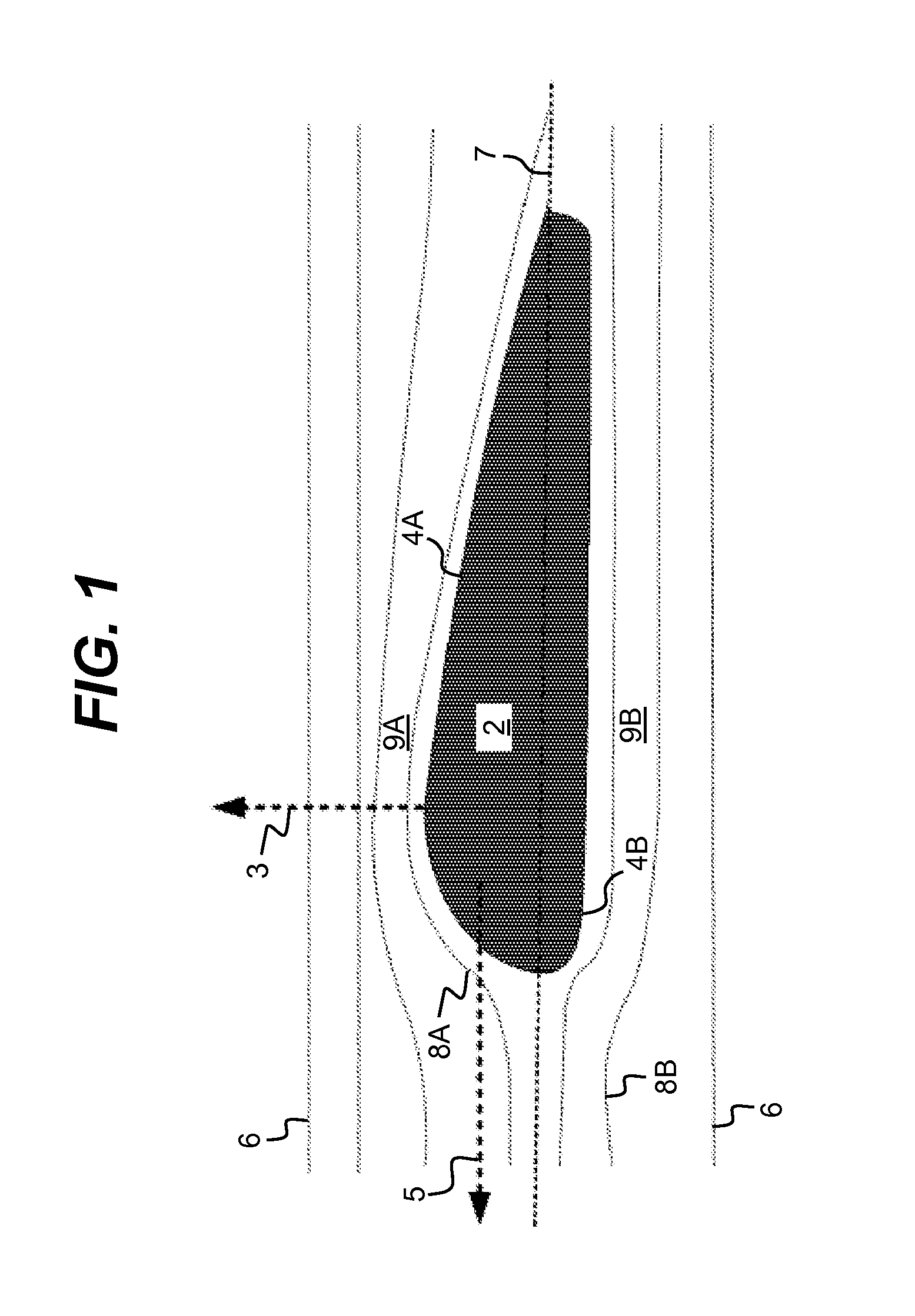
[0022]Turning to the drawings, FIG. 1 illustrates basic principles of aerodynamics relevant to a pressure profiling system described herein. In particular, FIG. 1 illustrates the evaluation of pressure for a body (e.g., an...


PUM


Abstract

A solution for acquiring pressure data for an object, such as an airfoil, is provided. One or more pressure sensor nodes are utilized, each of which includes a set of pressure sensors and a processing component. The pressure sensor node(s) are affixed to the object in a manner that enables the pressure sensors to acquire pressure data for a set of locations on the surface of the object. A pressure sensor node also can include a wireless communications component to provide wireless communications between the pressure sensor node and a computer system.

Description

REFERENCE TO RELATED APPLICATIONS[0001]The current application claims the benefit of co-pending U.S. Provisional Application No. 61 / 849,908, titled “Wireless Pressure Profiling System,” which was filed on 5 Feb. 2013, and which is hereby incorporated by reference.TECHNICAL FIELD[0002]The disclosure relates generally to pressure profiling, and more particularly, to an improved solution for obtaining pressure data.BACKGROUND ART[0003]Current approaches for obtaining pressure and other information from the flow of air over airfoils and other surfaces utilize “port” holes in the airfoil surface. From these holes, individual tubes convey the pressure to a central location. The tubes, pressure registration components, and other data-acquisition devices are complex, weighty, and require clear space for routing them through the airfoil. Moreover, such runs of tubing and connections have a myriad of potential failure points, including pinched tubes, holes, seal leaks, faulty electrical conne...

Claims


Application Information

Patent Timeline
Patent Type & Authority Applications(United States)
IPC IPC(8): G01M9/06
CPCG01M9/06G01L15/00
Inventor MIAN, ZAHID F.MCKENNEY, BRUCESPOOR, RYK E.
Owner INT ELECTRONICS MACHINES
Learn More