Circularly polarizing plate, retardation plate for circularly polarizing plate, and organic electroluminescence display apparatus

Active Publication Date: 2016-01-14
FUJIFILM CORP
View PDF8 Cites 11 Cited by
  • Summary
  • Abstract
  • Description
  • Claims
  • Application Information

AI Technical Summary

Benefits of technology

[0006]Meanwhile, in recent years, display apparatuses represented by organic EL display apparatuses have been required to further suppress mixing of black with another color observed in the front direction so as to further improve the image quality. More specifically, cur

Problems solved by technology

More specifically, currently, organic EL display apparatuses using a circularly polarizing plate have a problem that a coloring which is seemingly a mixture of black and other colors (mixing of black with other c

Method used


Image

  • Circularly polarizing plate, retardation plate for circularly polarizing plate, and organic electroluminescence display apparatus
  • Circularly polarizing plate, retardation plate for circularly polarizing plate, and organic electroluminescence display apparatus
  • Circularly polarizing plate, retardation plate for circularly polarizing plate, and organic electroluminescence display apparatus

Examples


first embodiment

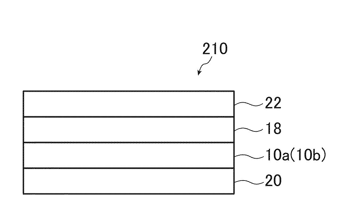
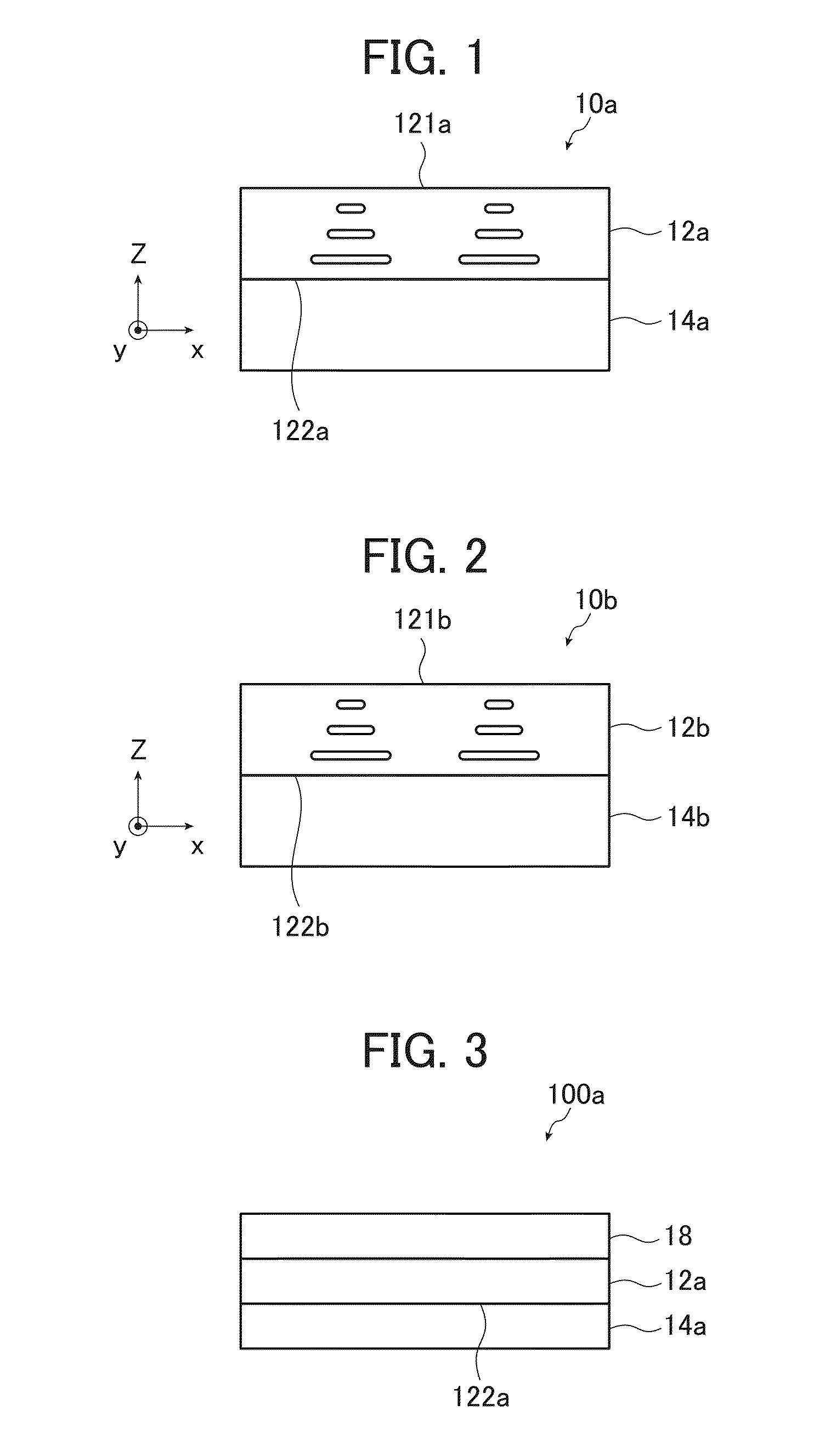
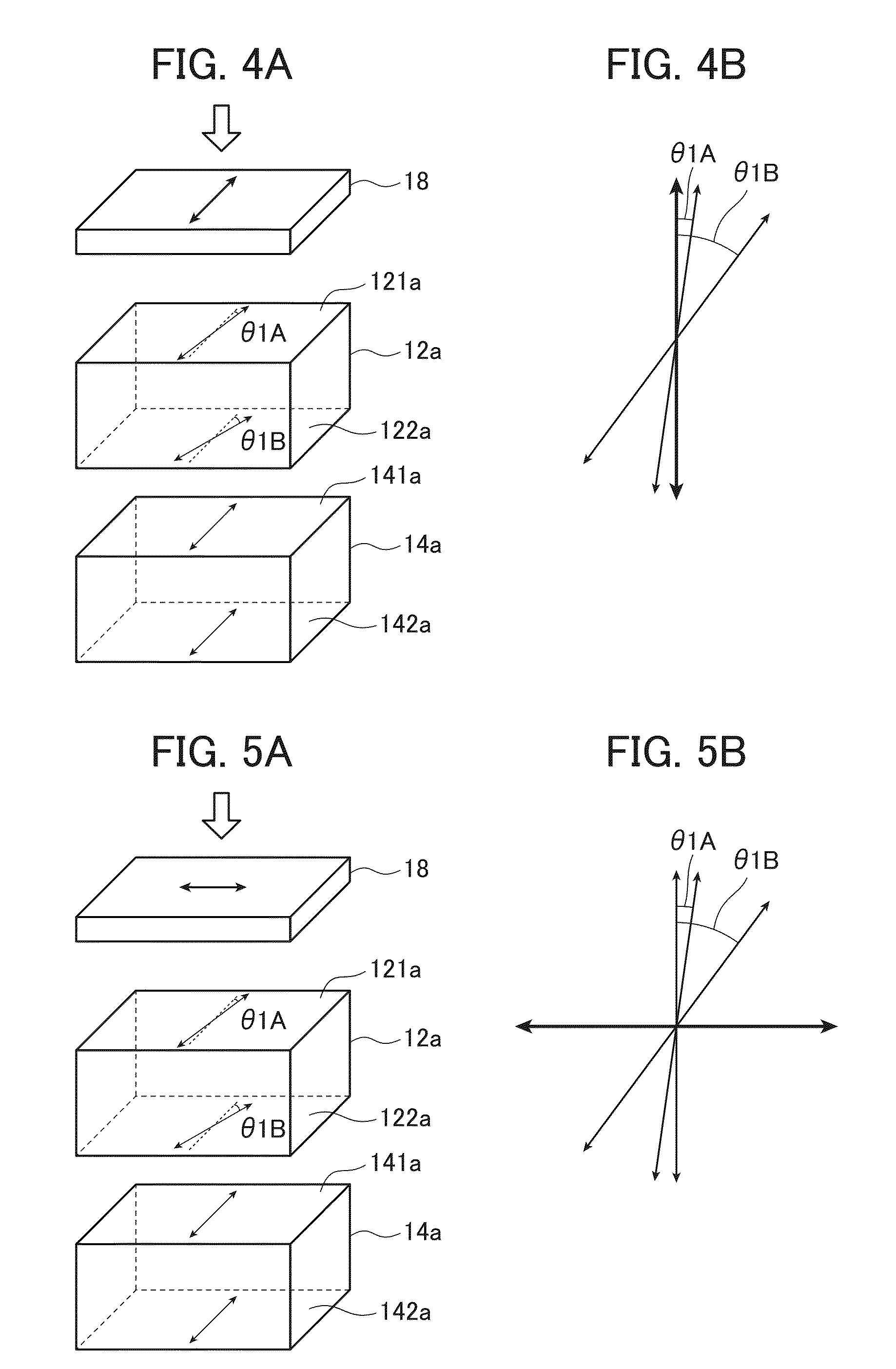
[0172]As a first embodiment of the circularly polarizing plate, a circularly polarizing plate 100a, which has the polarizing film 18, the first optically anisotropic layer 12a, and the second optically anisotropic layer 14a in this order as shown in FIG. 3, is exemplified

[0173]In the circularly polarizing plate 100a, the relationship between the absorption axis of the polarizing film 18 and the in-plane slow axis of the second optically anisotropic layer 14a satisfies the following requirement (X) or (Y).

[0174](X) The absorption axis of the polarizing film 18 and the in-plane slow axis of the second optically anisotropic layer 14a are parallel to each other.

[0175](Y) The absorption axis of the polarizing film 18 and the in-plane slow axis of the second optically anisotropic layer 14a are orthogonal to each other.

[0176]The relationship between the absorption axis of the polarizing film 18, the in-plane slow axis of the first optically anisotropic layer 12a, and the in-plane slow axis...

second embodiment

[0194]As a second embodiment of the circularly polarizing plate, a circularly polarizing plate 100b, which has the polarizing film 18, the first optically anisotropic layer 12b, and the second optically anisotropic layer 14b in this order as shown in FIG. 6, is exemplified

[0195]In the circularly polarizing plate 100b, the relationship between the absorption axis of the polarizing film 18 and the in-plane slow axis of the second optically anisotropic layer 14b satisfies the following requirement (Z) or (W).

[0196](Z) The absorption axis of the polarizing film 18 and the in-plane slow axis of the second optically anisotropic layer 14b are parallel to each other.

[0197](W) The absorption axis of the polarizing film 18 and the in-plane slow axis of the second optically anisotropic layer 14b are orthogonal to each other.

[0198]The relationship between the absorption axis of the polarizing film 18, the in-plane slow axis of the first optically anisotropic layer 12b, and the in-plane slow axi...

example 1

[0242](Alkaline Saponification Processing)

[0243]The support 3 was passed through a dielectric heating roll at 60° C. to increase the film surface temperature to 40° C., and then the band surface of the film was coated with an alkaline solution that had the following composition by using a bar coater at a coating amount of 14 ml / m2. The resultant was transported for 10 seconds under a steam-type far infrared heater manufactured by Noritake, Co, Limited, heated at 110° C., and then coated with pure water at 3 ml / m2 by using the same bar coater. Thereafter, the resultant was washed three times with water by using a fountain coater, drained three times by using an air knife, and dried by being transported for 10 seconds in a drying zone at 70° C., whereby a cellulose acylate film having undergone alkaline saponification processing was prepared.

[0244](Composition of Alkaline Solution)

[0245]Composition of Alkaline Solution (Part(s) by Mass)

Potassium hydroxide4.7parts by massWater15.8parts...


PUM


Abstract

A circularly polarizing plate includes a polarizing film, a first optically anisotropic layer, and a second optically anisotropic layer in this order, in which the first optically anisotropic layer contains a twisted aligned liquid crystal compound of which a helical axis is a thickness direction thereof, a helix angle of the liquid crystal compound is 28.6±10°, an absorption axis of the polarizing film and an in-plane slow axis of the second optically anisotropic layer are parallel or orthogonal to each other, Δnd and ReB(550) respectively fall in predetermined value ranges. The circularly polarizing plate can sufficiently suppress the mixing of black with other colors in a front direction when being stuck on a display apparatus. A retardation plate used for the circularly polarizing plate and an organic EL display apparatus that have the circularly polarizing plate are also provided.

Description

CROSS-REFERENCE TO RELATED APPLICATIONS[0001]This application is a Continuation of PCT International Application No. PCT / JP2014 / 058072 filed on Mar. 24, 2014, which claims priority under 35 U.S.C. §119(a) to Japanese Patent Application No. 2013-062443 filed on Mar. 25, 2013. The above application is hereby expressly incorporated by reference, in its entirety, into the present application.BACKGROUND OF THE INVENTION[0002]The present invention relates to a circularly polarizing plate, particularly, to a circularly polarizing plate having an optically anisotropic layer containing a twisted aligned liquid crystal compound.[0003]The present invention also relates to a retardation plate for a circularly polarizing plate used for the aforementioned circularly polarizing plate and relates to an organic electroluminescence (EL) display apparatus.[0004]Retardation plates are extremely versatile and are used for reflective LCDs, transflective LCDs, brightness enhancement films, organic EL disp...

Claims


Application Information

Patent Timeline
IPC IPC(8): G02B5/30H01L27/32H01L51/52
CPCG02B5/3083G02B5/3016H01L27/3232H01L51/5281G02B5/3025G02B5/3033H10K59/8791H10K50/86H10K59/50
Inventor SAITOH, YUKITOSATO, HIROSHIICHIHASHI, MITSUYOSHI
Owner FUJIFILM CORP
Why Eureka
Try Eureka