
Liquid Crystal Display and Optical Compensation Method Applied in Liquid Crystal Display

a liquid crystal display and optical compensation technology, applied in the field of lcd, can solve the problems of increased liquid crystal consumption, increased production cost, and non-relationship of opd, and achieve the effect of low contrast ratio

Inactive Publication Date: 2016-01-14
SHENZHEN CHINA STAR OPTOELECTRONICS TECH CO LTD
View PDF2 Cites 2 Cited by
  • Summary
  • Abstract
  • Description
  • Claims
  • Application Information

AI Technical Summary

Benefits of technology

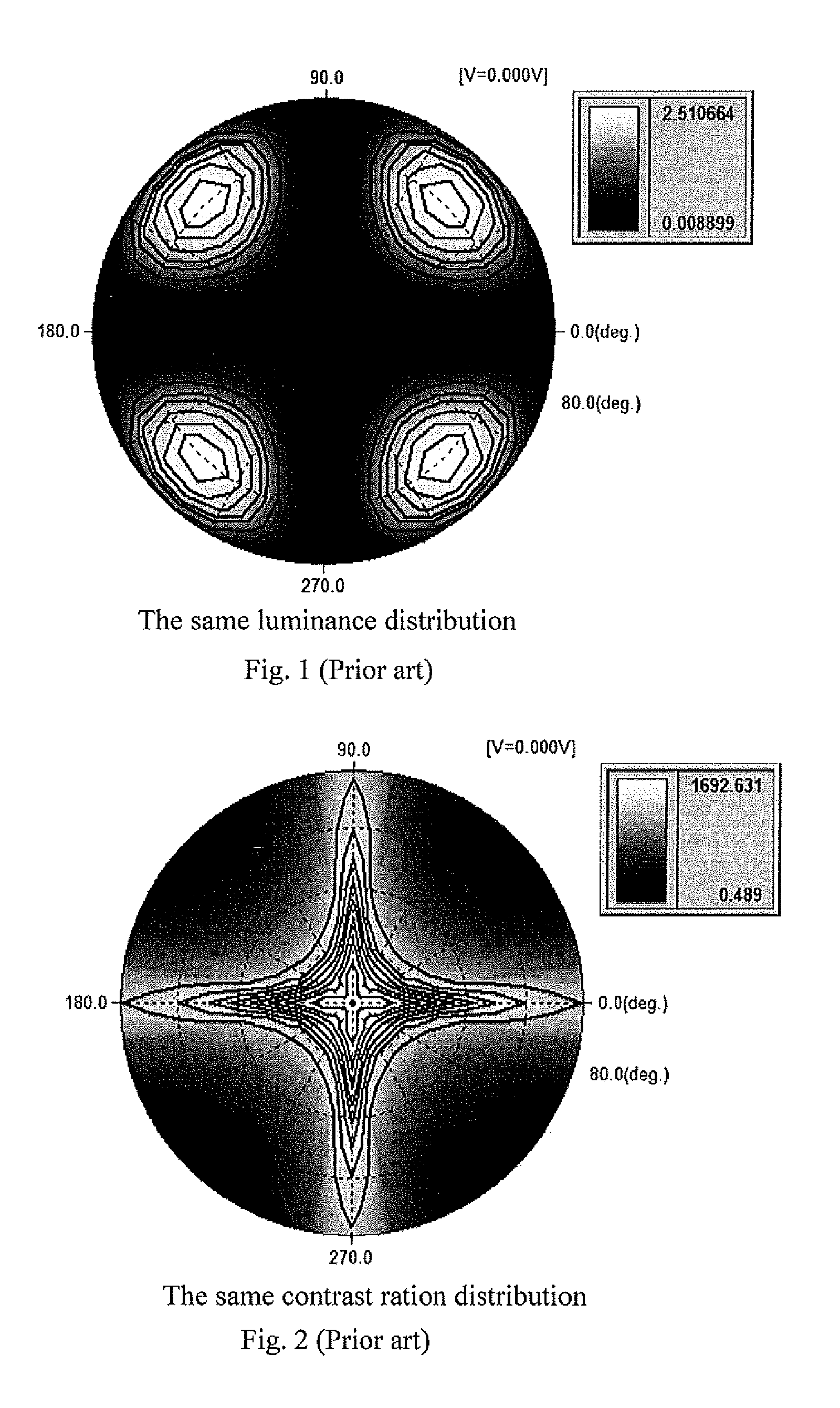
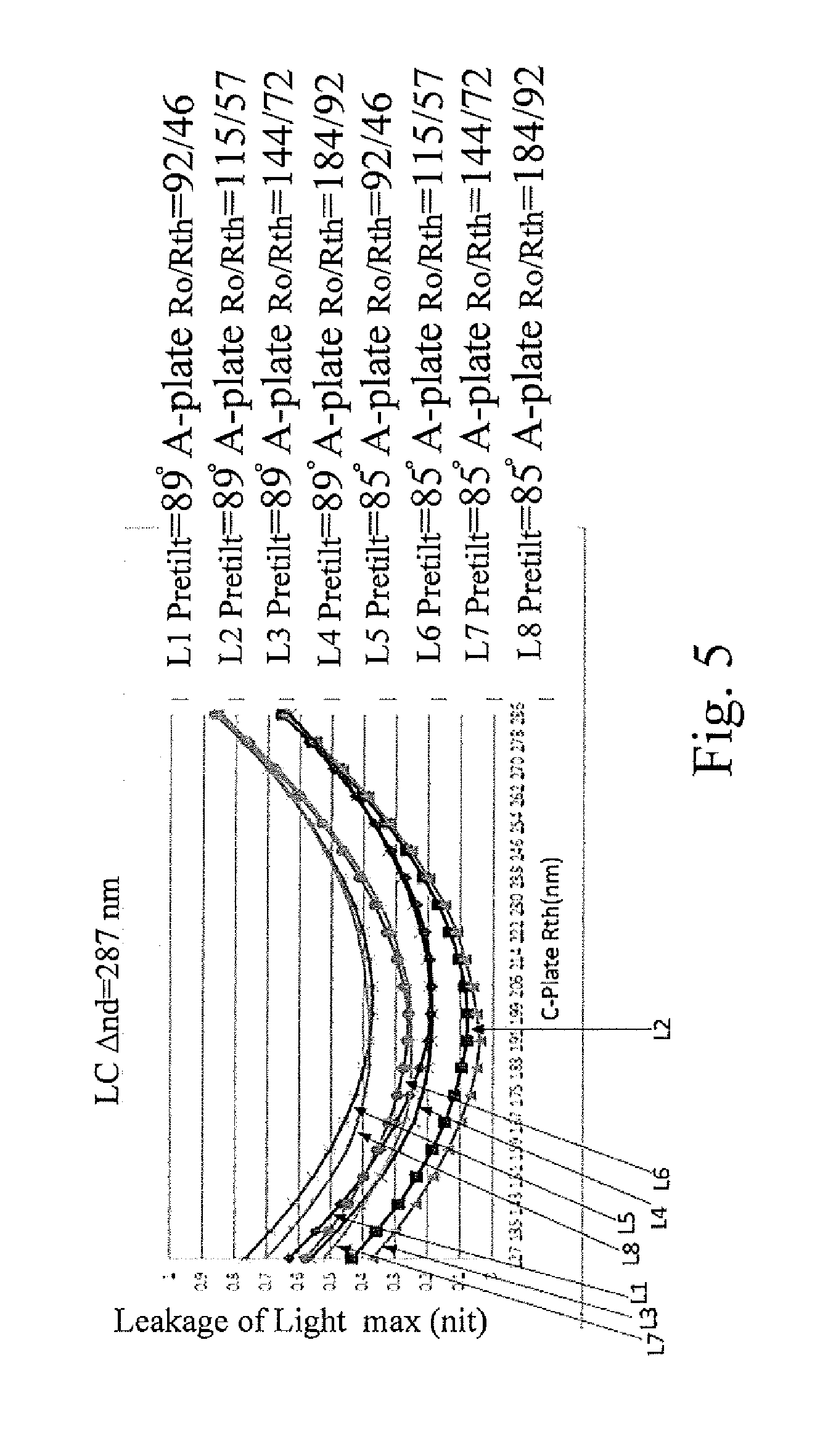
The present invention provides an LCD panel and an optical compensation method that solves the problem of severe leakage light and low contrast ratio under wide viewing angle observation. By changing compensation values of A-Plate and C-Plate, the invention weakens leakage light and increases wide viewing angle contrast ratio and resolution.

Problems solved by technology

To achieve higher liquid crystal optical path difference (OPD), cell gap of liquid crystal has to increase when refractivity is fixed, which leads to increase of liquid crystal consumption.
As liquid crystal is very costly, the more consumption of liquid crystal, the higher producing cost is.
Moreover, OPD not only relates to index of transmissivity, but also affects wide viewing angle leakage light.
Therefore, technical problems above mentioned await solution.

Method used


Image

  • Liquid Crystal Display and Optical Compensation Method Applied in Liquid Crystal Display
  • Liquid Crystal Display and Optical Compensation Method Applied in Liquid Crystal Display
  • Liquid Crystal Display and Optical Compensation Method Applied in Liquid Crystal Display

Examples


Embodiment Construction

[0048]Spatially relative terms, such as “beneath”, “below”, “lower”, “above”, “upper” and the like, may be used herein for ease of description to describe one element or feature's relationship to another element(s) or feature(s) as illustrated in the figures. It will be understood that the spatially relative terms are intended to encompass different orientations of the device in use or operation in addition to the orientation depicted in the figures.

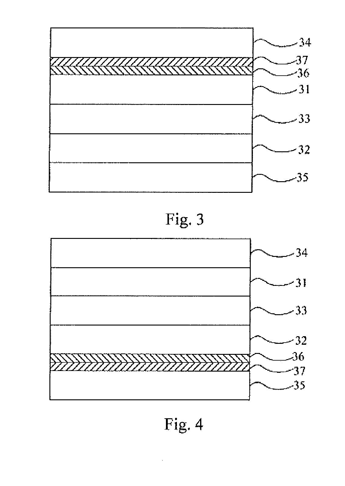
[0049]Please refer to FIG. 3, a structural diagram of the first preferred embodiment of LCD panels in the present invention.

[0050]The LCD of the embodiment in the present invention is preferably a vertical alignment (VA) LCD, whose optical path difference (OPD) LCΔND ranges 287 nm≦LCΔND≦305 nm, i.e. range [287 nm, 305 nm]; pretilt angle of the LCD ranges 85°≦Pretilt angle<90°, i.e. range [85°, 90°).

[0051]In the first embodiment as FIG. 3 indicates, the LCD comprises a first substrate 31, an uniaxial positively birefringent A-Plate 36, a ...


PUM

PropertyMeasurementUnit
birefringentaaaaaaaaaa
thicknessaaaaaaaaaa
birefringenceaaaaaaaaaa

Abstract

The present invention provides an LCD and an optical compensating method applied in the LCD. By changing compensation values of an uniaxial positively birefringent A-Plate and an uniaxial negatively birefringent C-Plate, especially the compensation value Rth of the uniaxial negatively birefringent C-Plate, the present invention weakens leakage light under wide viewing angle; embodying the present invention can effectively increase wide viewing angle contrast ratio and resolution.

Description

CROSS REFERENCE TO RELATED APPLICATION[0001]The present application is based on, and claims priority from, Chinese application number 201410290951.7, filed Jun. 25, 2014, the disclosure of which is hereby incorporated by reference herein in its entirety.BACKGROUND OF THE INVENTION[0002]1. Field of the Invention[0003]The present invention relates to a liquid crystal display (LCD) technology field, more particularly, to an LCD panel and an optical compensation method thereof.[0004]2. Description of the Prior Art[0005]As LCD panels continuously dissipate, demand for LCD panels of high quality is rising. To achieve higher liquid crystal optical path difference (OPD), cell gap of liquid crystal has to increase when refractivity is fixed, which leads to increase of liquid crystal consumption. As liquid crystal is very costly, the more consumption of liquid crystal, the higher producing cost is.[0006]Moreover, OPD not only relates to index of transmissivity, but also affects wide viewing a...

Claims


Application Information

Patent Timeline
Patent Type & Authority Applications(United States)
IPC IPC(8): G02F1/13363G02F1/1335
CPCG02F1/13363G02F2413/11G02F1/133634G02F1/133528G02F1/1393G02F2413/13G02F2413/14
Inventor KANG, CHIHTSUNGHAI, BO
Owner SHENZHEN CHINA STAR OPTOELECTRONICS TECH CO LTD
Learn More