Dual-shaft synchronous transmission device

a synchronous transmission and dual shaft technology, applied in the direction of casings/cabinets/drawers, instruments, casings/cabinets/drawers details of electric instruments, etc., can solve the problems of unable to meet the requirements of light weight and thinning of electronic devices, and the distance between the two shafts of the dual-shaft synchronous transmission device can be hardly as small as possibl

Active Publication Date: 2016-01-14
FIRST DOME
View PDF1 Cites 39 Cited by
  • Summary
  • Abstract
  • Description
  • Claims
  • Application Information

AI Technical Summary

Benefits of technology

The present invention is for a small and thin dual-shaft synchronous transmission device that can be used in electronic devices. The device has a short distance between the two shafts, which allows for a thinner and lighter electronic device. The device includes a driver, a reactor, and a link unit, which are connected using spur gear structures or crown gear structures. When the driver is rotated, the link unit is driven in the opposite direction, allowing the two shafts to rotate synchronously in opposite directions. The synchronous transmission device is located between a main fixing plate and a subsidiary fixing plate, which are connected together using identical structures. The main and subsidiary fixing plates have grooves that can be filled with lubricant to keep the link unit smoothly rotated. The technical effects of this invention include a more compact and efficient dual-shaft synchronous transmission device that allows for thinner and lighter electronic devices.

Problems solved by technology

As a result, with the multiple conical gears, the distance between the two shafts of the dual-shaft synchronous transmission device can be hardly as minified as possible.
Especially, the transmission mechanism applied to the notebook or a mini-type electronic apparatus fails to meet the requirements of lightweight and thinning of the electronic apparatus.

Method used


Image

  • Dual-shaft synchronous transmission device
  • Dual-shaft synchronous transmission device
  • Dual-shaft synchronous transmission device

Examples


Embodiment Construction

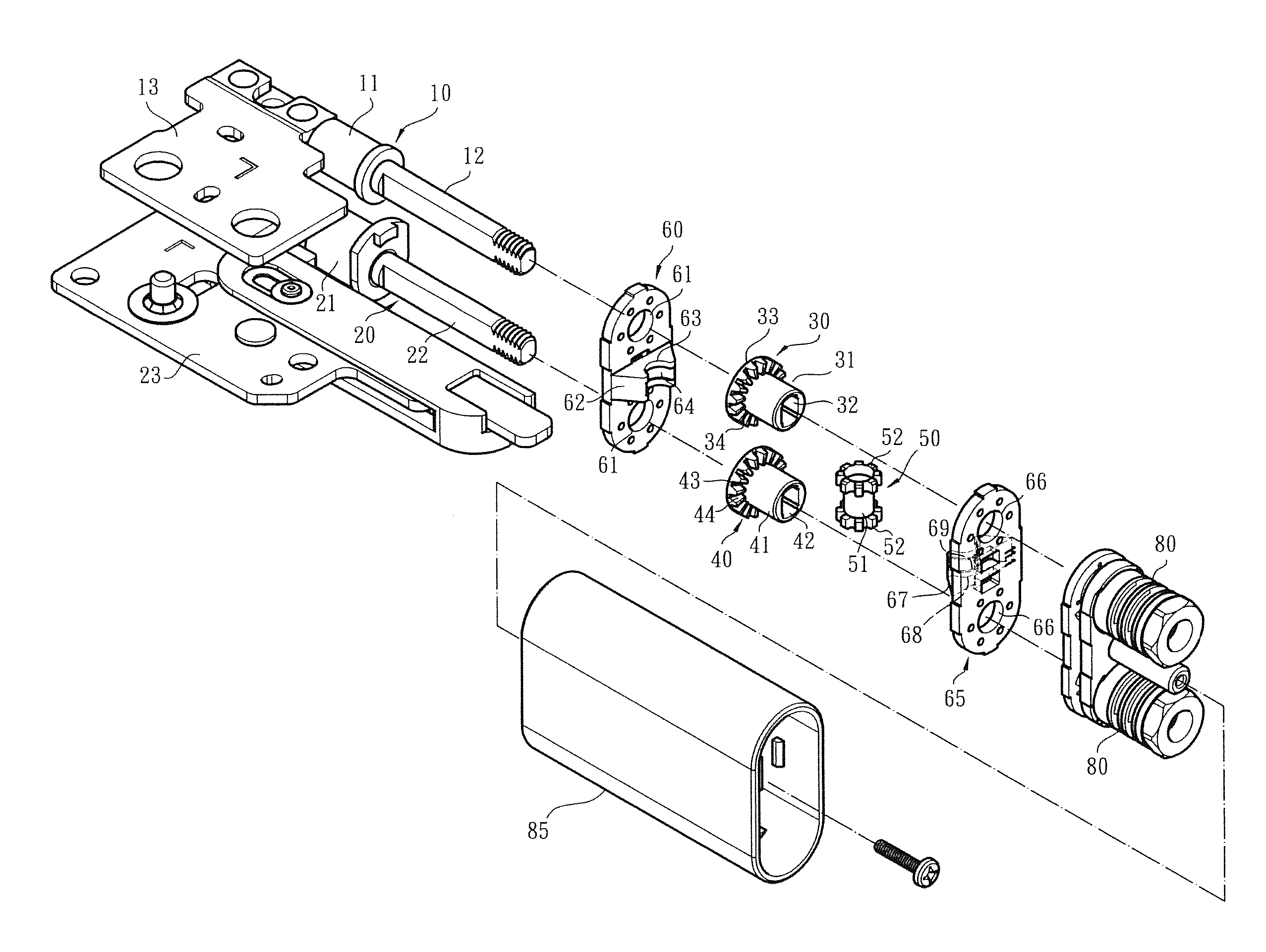
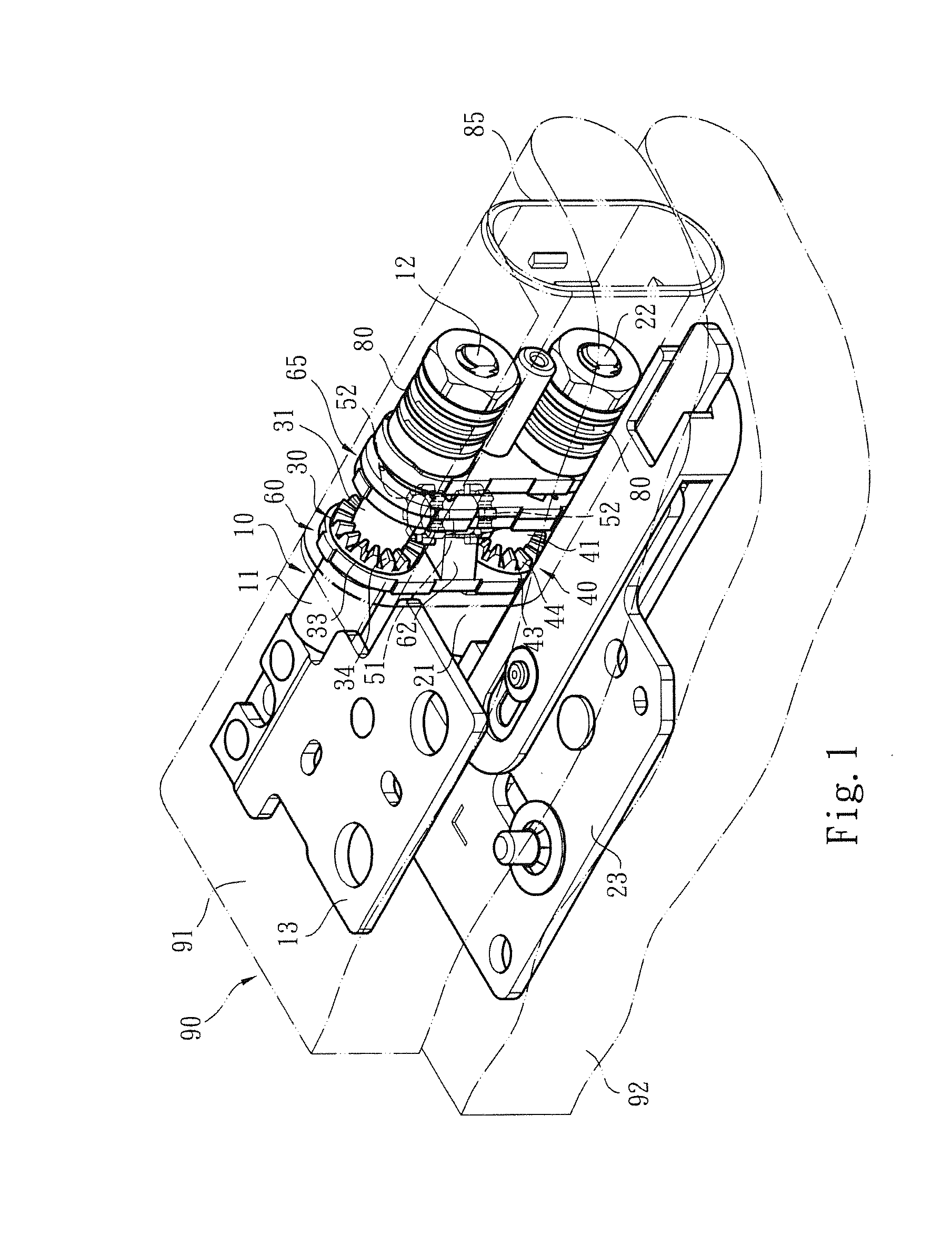
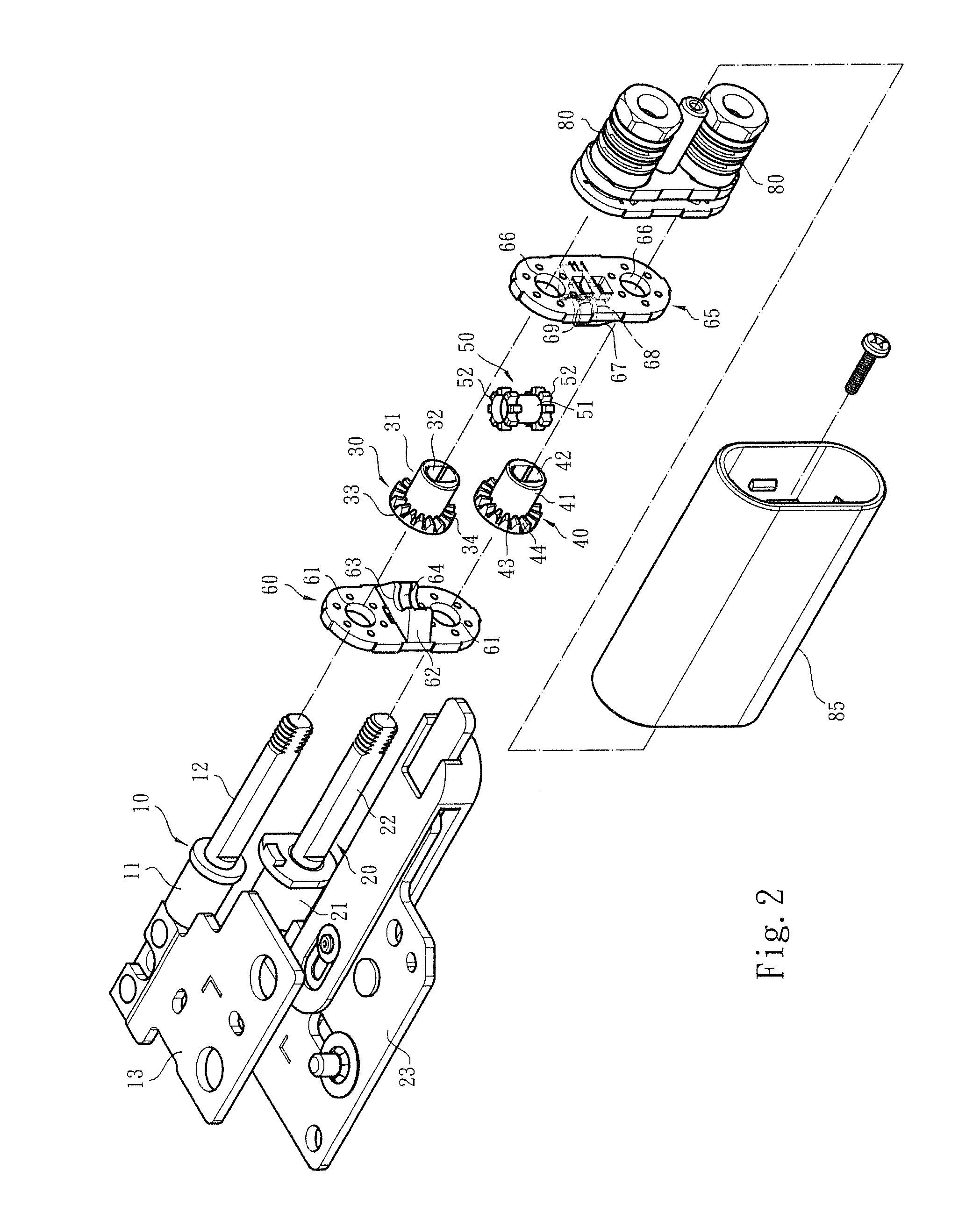
[0016]Please refer to FIGS. 1, 2 and 3. The dual-shaft synchronous transmission device of the present invention includes a first shaft 10 and a second shaft 20. Each of the first and second shafts 10, 20 has a fixed section 11, 21 and a pivoted section 12, 22. The fixed sections 11, 21 are assembled with fixing seats 13, 23 to respectively fix the first and second shafts 10, 20 on a display module 91 and an apparatus body module 92 of an electronic apparatus 90 (such as a mobile phone, a computer or the like). The pivoted sections 12, 22 of the first and second shafts 12, 22 are (respectively) assembled with torque modules 80. Accordingly, when the action force applied to the display module 91 or the apparatus body module 92 by a user for rotating the same disappears, the display module 91 and the apparatus body module 92 are immediately located.

[0017]As shown in FIGS. 1, 2 and 3, the synchronous transmission device is disposed on the pivoted sections 12, 22 of the first and second ...


PUM


Abstract

A dual-shaft synchronous transmission device is applied to an electronic apparatus. The distance between the two shafts of the dual-shaft synchronous transmission device is shortened so that the electronic device can be thinned and lightweight. The dual-shaft synchronous transmission device includes a driver and a reactor respectively disposed on a first shaft and a second shaft and a link unit. Spur gear structures or crown gear structures are respectively disposed on the driver and the reactor. Crown gear structures or spur gear structures are respectively disposed at two ends of the link unit correspondingly engaged with the spur gear structures or crown gear structures of the driver and the reactor. When the first shaft and the driver are rotated, the driver rotates the link unit to drive the reactor and the second shaft to synchronously rotate in a direction reverse to the rotational direction of the driver.

Description

BACKGROUND OF THE INVENTION[0001]1. Field of the Invention[0002]The present invention relates to a dual-shaft synchronous transmission device, and more particularly to a dual-shaft synchronous transmission device in which spur structures and crown gear structures are cooperatively assembled to transmit power so as to synchronously rotate the first and second shafts.[0003]2. Description of the Related Art[0004]There are various electronic apparatuses provided with covers or display screens, such as mobile phones, notebooks, PDA, and electronic books. The covers or display screens are pivotally mounted on the electronic apparatuses via pivot pins or rotary shafts, whereby the covers or display screens can be freely rotated and opened / closed under external force. For example, a prior art discloses a rotary shaft structure and another prior art discloses a pivot pin structure.[0005]In order to operate the display module (such as the screen) and / or the apparatus body module of the electr...

Claims


Application Information

Patent Timeline
IPC IPC(8): G06F1/16H05K5/02
CPCH05K5/0226G06F1/1681H04M1/022E05D3/122E05Y2999/00
Inventor HSU, AN SZULEE, WANG JUILIN, CHUNG YILIN, YA CHING
Owner FIRST DOME
Why Eureka
Try Eureka