
Automatic spatial calibration of camera network

a technology of automatic calibration and camera network, applied in the field of camera calibration, can solve the problems of increasing the likelihood of detecting problems and increasing the visual coverage of the road

Active Publication Date: 2016-01-14
AGT INTERNATIONAL INC
View PDF6 Cites 33 Cited by
  • Summary
  • Abstract
  • Description
  • Claims
  • Application Information

AI Technical Summary

Benefits of technology

The present invention relates to improving the performance of a camera network by optimizing the positioning of cameras in relation to each other. Specifically, the invention seeks to minimize the difference in the position of the cameras' fields of view, which can cause misalignment. This global optimization reduces the likelihood of image quality degradation and improves overall visual performance.

Problems solved by technology

Placement of a network of cameras along a road may increase visual coverage of the road and increase the likelihood of detecting a problem.

Method used


Image

  • Automatic spatial calibration of camera network
  • Automatic spatial calibration of camera network
  • Automatic spatial calibration of camera network

Examples


Embodiment Construction

[0033]In the following detailed description, numerous specific details are set forth in order to provide a thorough understanding of the invention. However, it will be understood by those of ordinary skill in the art that the invention may be practiced without these specific details. In other instances, well-known methods, procedures, components, modules, units and / or circuits have not been described in detail so as not to obscure the invention.

[0034]Although embodiments of the invention are not limited in this regard, discussions utilizing terms such as, for example, “processing,”“computing,”“calculating,”“determining,”“establishing”, “analyzing”, “checking”, or the like, may refer to operation(s) and / or process(es) of a computer, a computing platform, a computing system, or other electronic computing device, that manipulates and / or transforms data represented as physical (e.g., electronic) quantities within the computer's registers and / or memories into other data similarly represe...


PUM


Abstract

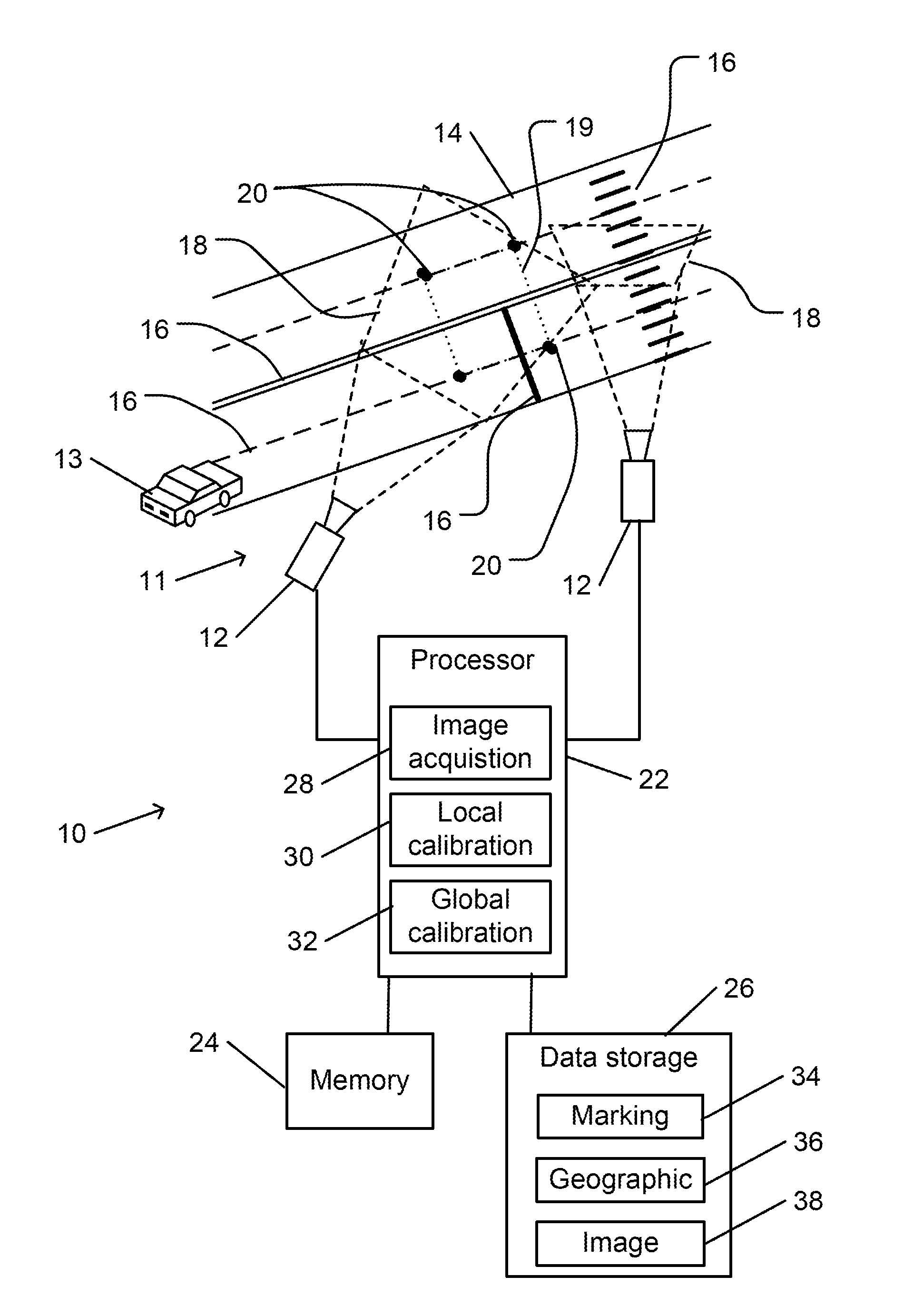
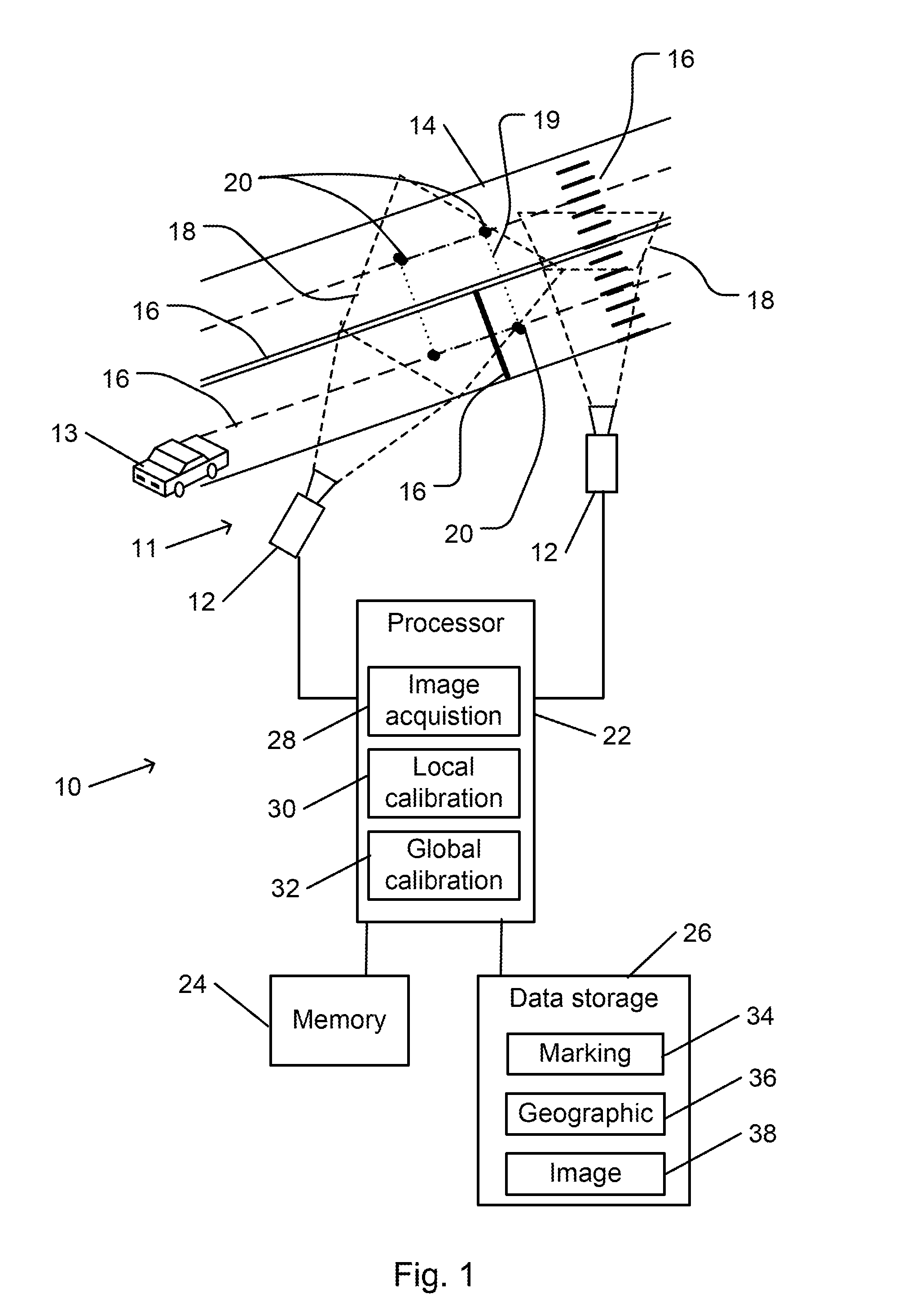
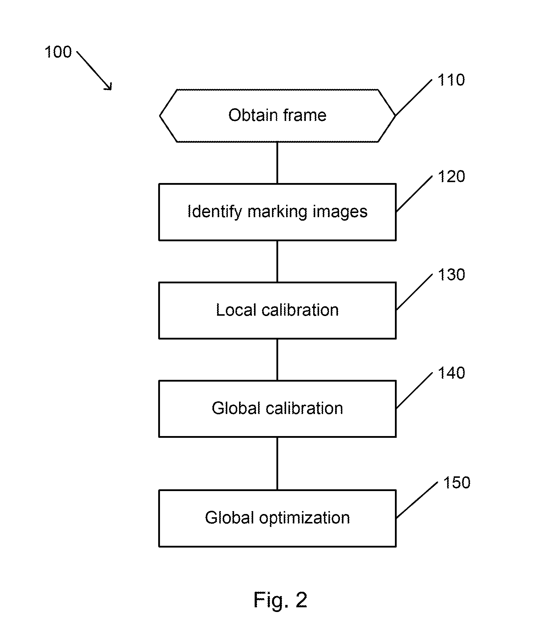
A method for automatic spatial calibration of a network of cameras along a road includes, processing a frame that is obtained from each camera of the network to automatically identify an image of a pattern of road markings that have a known spatial relationship to one another. The identified images are used to calculate a position of each camera relative to the pattern of road markings that is imaged by that camera. Geographical information is applied to calculate an absolute position of a field of view of each camera. A global optimization is applied to adjust the absolute position of the field of view of each camera of the camera network relative to an absolute position of the fields of view of other cameras of the camera network

Description

CROSS REFERENCE TO RELATED APPLICATIONS[0001]The present invention claims the priority benefit of U.S. provisional patent application No. 62 / 023,283 filed on Jul. 11, 2014, which is incorporated in its entirety herein by reference.FIELD OF THE INVENTION[0002]The present invention relates to camera calibration. More particularly, the present invention relates to spatial calibration of a camera network.BACKGROUND OF THE INVENTION[0003]Surveillance cameras are often positioned along roads to monitor traffic on the road. The cameras may serve the purpose of deterring or detecting traffic violations or criminal activity along the road. The cameras may detect road conditions or traffic conditions that require attention from appropriate government, road maintenance, or law enforcement authorities. Images that are acquired by the cameras may be monitored by human observers, may be subjected to automatic analysis by an computer or processor, or both.[0004]Placement of a network of cameras al...

Claims


Application Information

Patent Timeline
IPC IPC(8): G06T7/00G06T7/20G06T17/05G08G1/04H04N5/247H04N7/18
CPCG06T7/0018G06T7/004G06T7/2093G06T17/05H04N5/247H04N7/181G06T2210/61G06T2200/21G06T2207/10004G06T2207/20008G06T2207/30232G06T2207/30241G08G1/04G06T2207/30244G06T2207/30256G06T7/80H04N23/90
Inventor HAMER, HENNINGSAWCHUK, ARSENIISCHLATTMANN, MARKUSHEREMANS, ROEL
Owner AGT INTERNATIONAL INC
Learn More