Protocol for an electronic device to receive a data packet from an external device

a technology of electronic devices and data packets, applied in the field of electronic devices, can solve the problems of high energy consumption, inability to replace batteries, and high energy consumption, and achieve the effects of less energy consumption, greater current, and energy saving

Active Publication Date: 2016-01-14
RGT UNIV OF MICHIGAN
View PDF9 Cites 10 Cited by
  • Summary
  • Abstract
  • Description
  • Claims
  • Application Information

AI Technical Summary

Benefits of technology

[0018]In some cases, before receiving the data packet, the electronic device and external device may exchange messages to signal that the devices are ready for the data packet transmission. Hence, the control unit may control the receiver to detect a beacon transmitted from the external device signalling that the external device is ready to transmit a data packet, and in response to detecting the beacon, may control the transmitter to transmit a beacon acknowledgment to signal that the electronic device is ready to receive the data packet. This can be useful for energy saving to allow the electronic device to enter deeper power saving modes in which less energy is consumed. When the external device wishes to communicate with the electronic device, the external device can periodically send beacon messages to the electronic device, until the electronic device responds. The electronic device may periodically be woken up from the sleep mode to an active mode, check whether a beacon has been transmitted from the external device, and if no beacon is detected switch back to sleep mode to save energy. If a beacon has been detected then a beacon acknowledgement can be sent to the external device. The external device may continue to transmit beacons until it receives an acknowledgment, and then to transmits the data stream including the repeated data packet as discussed above.
[0019]The device may have a charge reservoir for supplying power to the receiver. For example the charge reservoir may be a capacitor which can be charged with power supplied by a battery or an energy harvesting unit for harvesting ambient energy (e.g. a solar cell, thermoelectric device or piezoelectric device). This is particularly useful where the charge reservoir is charged from a small battery such as thin film battery which can only provide a limited amount of current. By accumulating charge in the charge reservoir, this enables a greater current to be supplied to the transmitter or receiver, which may not be able to function based on the smaller current supplied directly from the battery. However, powering the transmitter or receiver from the charge reservoir limits the length of time for which the transmitter or receiver can be continuously active before the charge in the charge reservoir is depleted. The present technique is very useful for a device having a charge reservoir, because it enables the electronic device to communicate with the external device using short bursts of activity at the transmitter or receiver, allowing time for replenishing the charge reservoir in between. Also, by reducing the amount of time for which the receiver has to be active to capture the data packet and avoiding the need to scan the receive stream for the header portion before capturing the data packet, the present technique allows more efficient use of the charge stalled by the charge reservoir. This means that the same amount of charge can support a greater transmission / reception power, so that the electronic device can communicate with the external device over an increased distance. For example, by using the protocol discussed above, a receiver has been built which is the first ever millimetre-sized receiver which can achieve 1 metre of range while running off a mm-sized thin-film battery.

Problems solved by technology

For such a device, there are severe constraints on both the amount of energy available for the device and the peak current which can be supplied to the radio transmitter / receiver.
For example, it may not be practical to replace a battery in a device that is implanted in the body, and the device may need to function for a long period of time, so energy efficiency may be important.
Many current protocols for communicating with such a device require an accurate jitter-free timing reference, which is expensive in terms of energy.
This approach may seem counterintuitive, since transmitting the same data packet many times from the external device will increase the power consumed by the external device, and increase the amount of bandwidth used, and reduce the bit rate available.
Also, since the data packet can be captured and rotated into the correct format regardless of the timing of the capture window relative to the data stream, there is no need for an accurate timing reference clock or jitter free clock, which incurs an energy cost.
Firstly, the delay provides time for energy to be harvested by an energy harvesting unit, or charge to be accumulated in a charge reservoir, to provide enough energy to power the transmitter, which is useful since the energy or charge may have been depleted following the receiver capturing the data packet.
By accumulating charge in the charge reservoir, this enables a greater current to be supplied to the transmitter or receiver, which may not be able to function based on the smaller current supplied directly from the battery.
However, powering the transmitter or receiver from the charge reservoir limits the length of time for which the transmitter or receiver can be continuously active before the charge in the charge reservoir is depleted.
Hence, there may be a delay before the next reception or transmission while the charge reservoir is being recharged.
Hence, the transmitting device incurs increased energy cost and uses more bandwidth for the transmission by repeating the same data packet several.

Method used


Image

  • Protocol for an electronic device to receive a data packet from an external device
  • Protocol for an electronic device to receive a data packet from an external device
  • Protocol for an electronic device to receive a data packet from an external device

Examples


Embodiment Construction

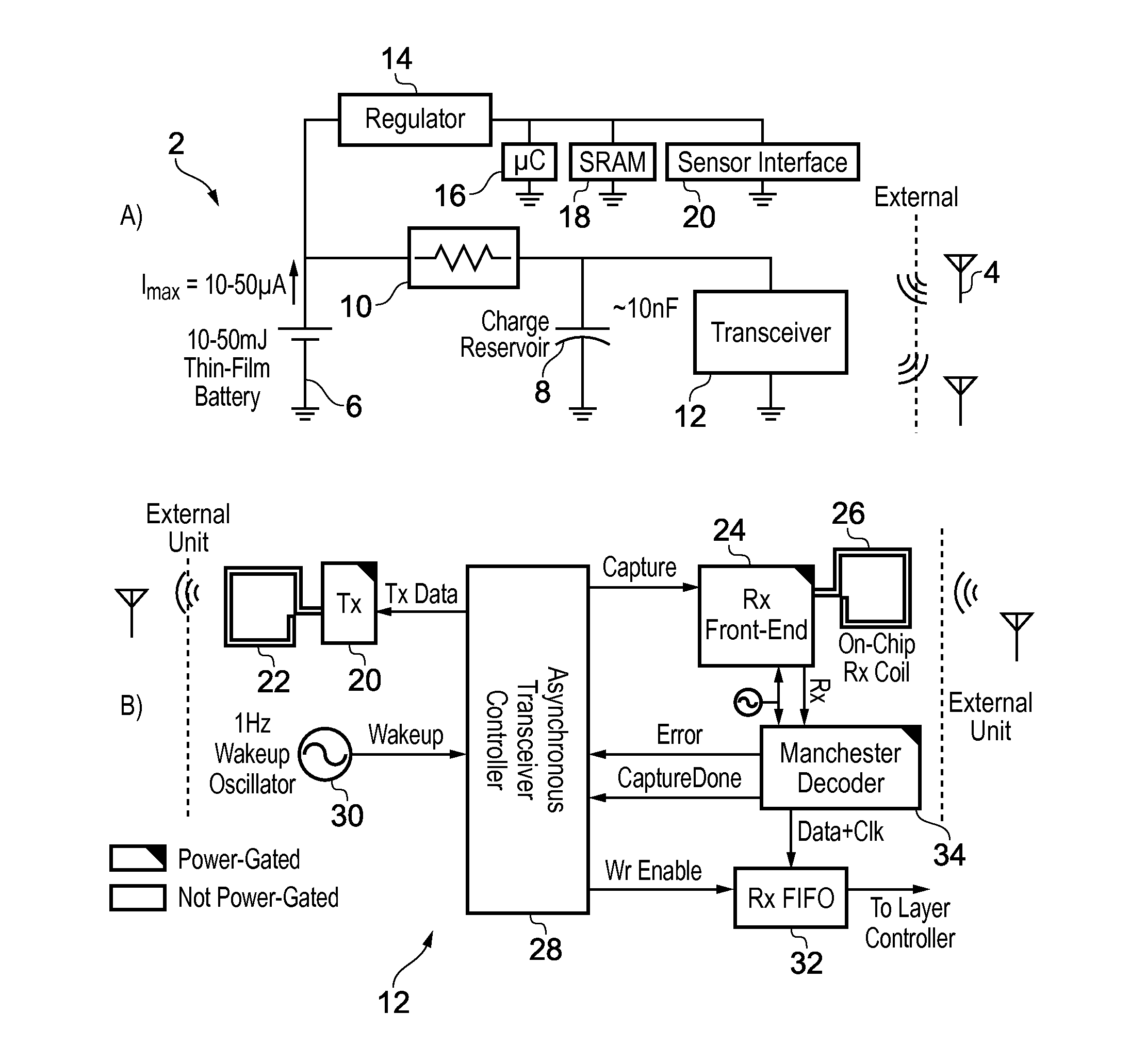
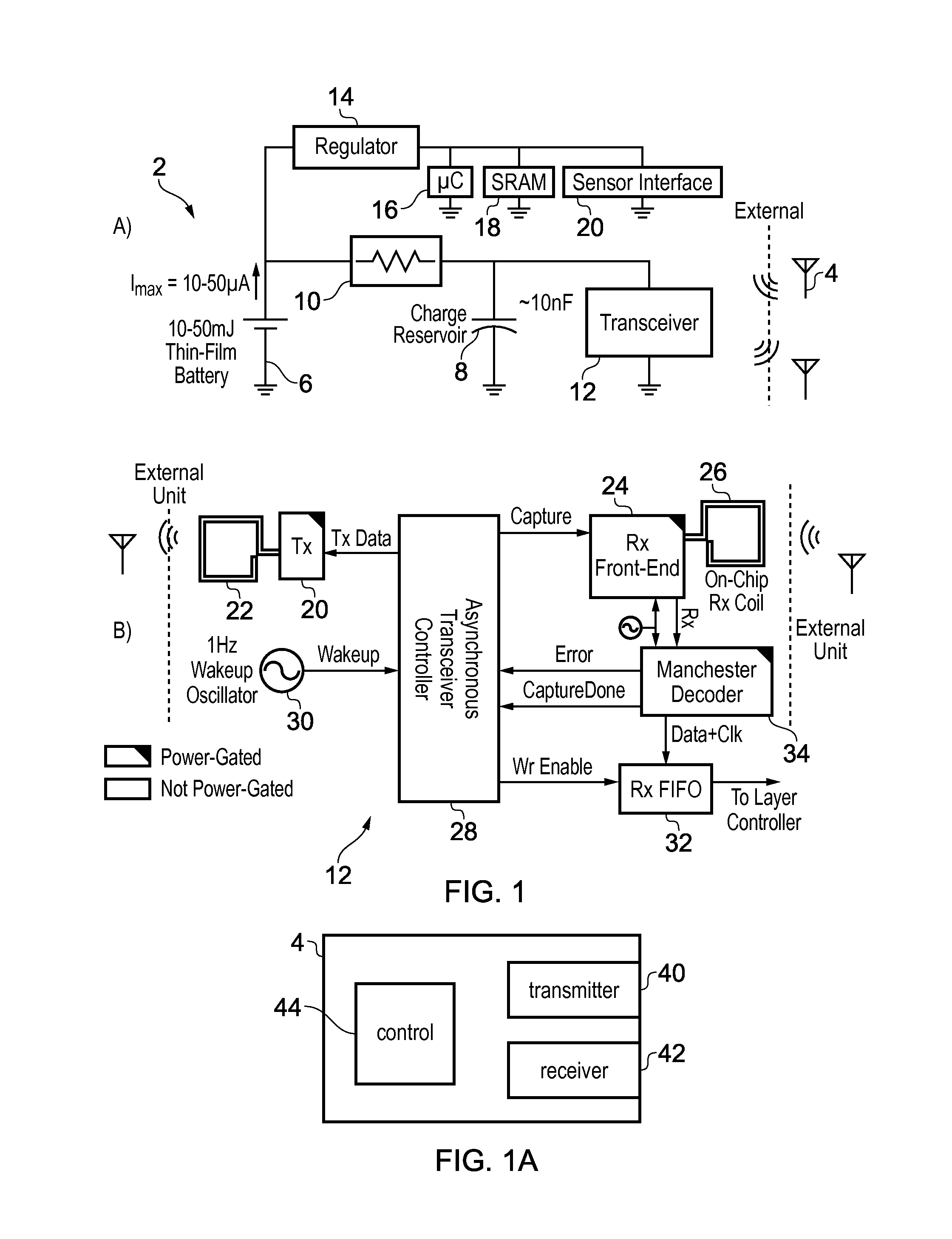
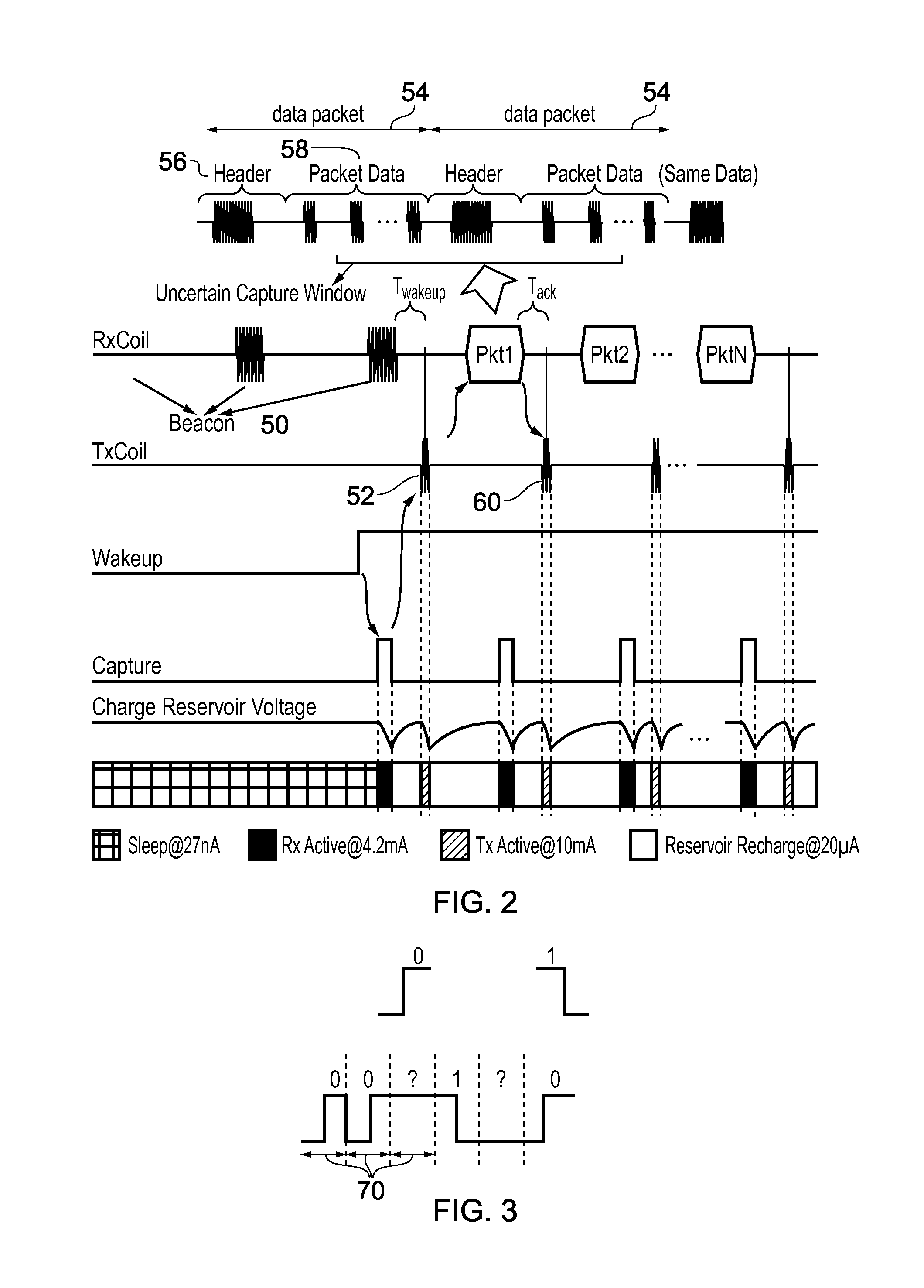
[0046]Short communication range wireless sensor nodes are in great demand for intracranial, intraocular and cardiac applications, among others. One differentiating feature of such nodes is their highly miniaturized form factors, often in the mm range. As a result, the substantial work in low power RFID is incompatible with this emerging class of devices due to the large antennas of RFID card-type devices. Current near-field solutions require large peak currents not feasible in such systems. Very small (1-10 mm2) thin-film batteries offer a reliable power source for such systems. While their 10-50 mJ capacities are sufficient for the transmission of several Mb between battery recharges (at 1 nJ / bit), their peak output current of 10-50 μA is inconsistent with RF blocks (mA range). Therefore, these blocks may operate using a capacitive charge reservoir (nF range) that is recharged between radio transmissions. However, ms range recharge times reduce bit rate and place tighter requiremen...


PUM


Abstract

A protocol for transmitting data from an external device to an electronic device is provided in which the external device transmits a data stream which includes the same data packet repeated multiple times. The data packet has a predetermined length and has a header portion at a predetermined position. A receiver at the electronic device captures a block of data having the predetermined length from the transmitted data stream, and a decoder rotates the captured block of data to place the header portion at the predetermined position within the data packet. This eliminates the need for an accurate jitter-free clock reference at the electronic device. By shifting power consumption and system complexity to the external unit where power is typically not constrained, the energy efficiency of the electronic device can be increased.

Description

BACKGROUND[0001]1. Technical Field[0002]The present technique relates to the field of electronic devices. More particularly, it relates to a technique for receiving a data packet from an external device.[0003]2. Technical Background[0004]There is an increasing demand for electronic devices which are both very small and energy efficient. For example, wireless sensor nodes which can communicate at relatively short range with an external device are in demand for biomedical applications such as intracranial, intraocular, or cardiac sensors which can be embedded in the body for transmitting sensing data to external device. For such a device, there are severe constraints on both the amount of energy available for the device and the peak current which can be supplied to the radio transmitter / receiver. For example, it may not be practical to replace a battery in a device that is implanted in the body, and the device may need to function for a long period of time, so energy efficiency may be...

Claims


Application Information

Patent Timeline
Patent Type & Authority Applications(United States)
IPC IPC(8): H04L29/06H04B1/034H04W4/80H04W52/02
CPCH04L69/22H04W52/0209H04B1/034H04W4/008H04W4/80Y02D30/70
Inventor GHAED, MOHAMMAD HASSANSKRZYNIARZ, SKYLARBLAAUW, DAVID THEODORESYLVESTER, DENNIS MICHAEL
Owner RGT UNIV OF MICHIGAN
Why Eureka
Try Eureka