Emergency Braking System for a Vehicle

Inactive Publication Date: 2016-01-21
JAGUAR LAND ROVER LTD
View PDF6 Cites 31 Cited by
  • Summary
  • Abstract
  • Description
  • Claims
  • Application Information

AI Technical Summary

Benefits of technology

[0077]It is clear that longer range ultrasonic sensors are of greater use and will cover approximately 50% of pedestrian tests currently proposed by Euro NCAP, which range in vehicle speeds from 10 to

Problems solved by technology

Many accidents are caused by late braking and/or braking with insufficient force.
A driver may brake too late for several reasons: he/she is distracted or inattentive; visibility is poor, for instance when driving towards a low sun; or a situation may be very difficult to predict because the driver ahead is braking unexpectedly.
Most people are not used to dealing with such critical situations and do not apply enough braking force to avoid a crash.
Firstly, when the system calculates that a collision is likely, it issues optical and acoustic warnings and pre-fills the braking system in preparation for an avoidance manoeuvre by the driver.
If the driver remains inactive (no steering or braking input), the car applies the brakes automatically and reduces engine torque.
Again, such invocation cannot reasonably be commenced before a collision becomes inevitable because drivers need to remain in control of, and be responsible for the driving of, their vehicl

Method used


Image

  • Emergency Braking System for a Vehicle
  • Emergency Braking System for a Vehicle
  • Emergency Braking System for a Vehicle

Examples


Example

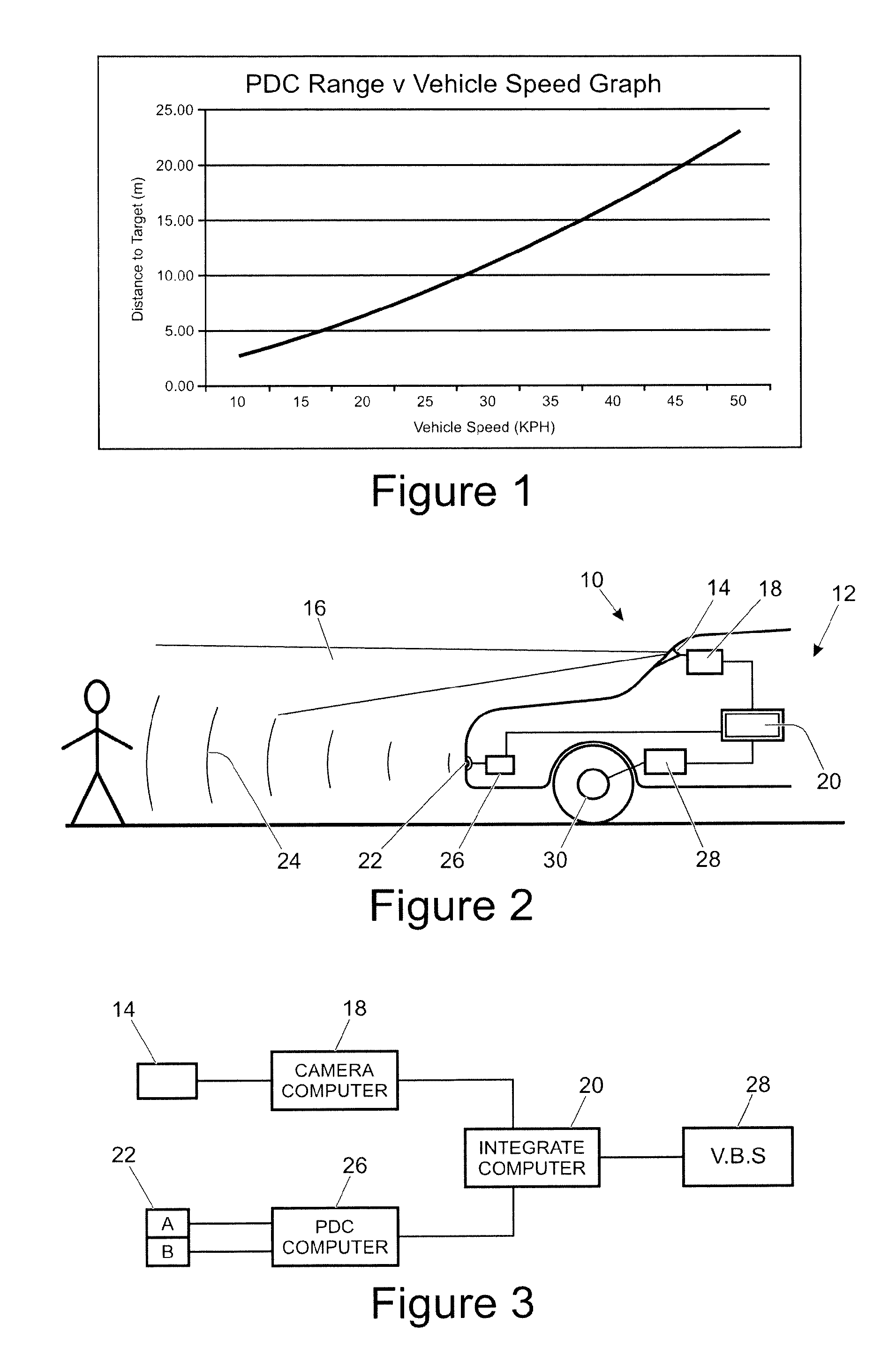
[0084]In FIG. 1, a graph is plotted of the distance from a target that a PDC system is capable of detecting against vehicle speed. The graph uses equation (1) below to calculate the range (R) required to effect braking, taking into account the estimated transport delays in the system:

R=v*TPDC+v*TBD+SO+v2 / 2a  (1)

[0085]Where v is the vehicle speed, TPDC is the time it takes a system, the PDC, to make a decision (typically 0.3 seconds (s)), TBD is the time for the brakes to start operating and decelerating the vehicle (typically 0.3 s), SO is the distance from the object at which the vehicle should at a minimum come to a complete halt, a is the maximum deceleration (which depends on many environmental factors not possible to control, but typically may be set at 8.2 ms−2).

[0086]Equation (1) is based upon the following kinematic equation of linear motion:—

r=v22a(2)

[0087]From the graph it can be seen that with a range of 15 m, a PDC can operate at speeds up to 35-40 kph. However, if the d...


PUM


Abstract

Emergency Braking System for a Vehicle The invention relates to an Intelligent emergency braking (IEB) system and method for a vehicle. It comprises a camera (14), one or more ultrasonic transceivers (22) of a parking aid system and a computer (20). The camera is adapted to provide captured image data, and the transceivers provide transceiver data. The computer processes said data. The camera will invoke automatic braking if: i) the confidence with which the computer calculates that a detected object is a person or is an object vehicle exceeds a first predetermined level, and ii) the ultrasonic transceiver provides the computer with transceiver data consistent with the object detected through the captured image data.

Description

TECHNICAL FIELD[0001]This invention relates to a vehicle including an emergency braking system.BACKGROUND[0002]Many accidents are caused by late braking and / or braking with insufficient force. A driver may brake too late for several reasons: he / she is distracted or inattentive; visibility is poor, for instance when driving towards a low sun; or a situation may be very difficult to predict because the driver ahead is braking unexpectedly. Most people are not used to dealing with such critical situations and do not apply enough braking force to avoid a crash.[0003]Intelligent Emergency Braking (IEB) systems improve safety in two ways: firstly, they help to avoid accidents by identifying critical situations early and warning the driver; and secondly they reduce the severity of crashes which cannot be avoided by lowering the speed of collision and, in some cases, by preparing the vehicle and restraint systems for impact.[0004]Most IEB systems use radar or lidar-based technology to ident...

Claims


Application Information

Patent Timeline
IPC IPC(8): B60T7/22B60T8/171
CPCB60T8/171B60T7/22B60W10/18B60W30/09B60W2420/42B60W2420/54B60R21/013G08G1/166B60R2021/01013
Inventor PARKER, DIRKCOCKINGS, KEVINCUND, MARK
Owner JAGUAR LAND ROVER LTD
Why Eureka
Try Eureka