
Locking device

a technology of locking device and locking pin, which is applied in the direction of cylinder locks, keys, electric permutation locks, etc., can solve the problem that the plug cannot be rotated

Inactive Publication Date: 2016-01-21
HENRY SQUIRE & SONS
View PDF16 Cites 9 Cited by
  • Summary
  • Abstract
  • Description
  • Claims
  • Application Information

AI Technical Summary

Benefits of technology

The invention provides a lock that uses less power than previous designs. It uses a recess in a pin and a locking member to prevent the pin from engaging a key and rotating a plug. The locking member control device only needs to act for a short period of time, reducing power consumption and allowing for a smaller battery. This results in a longer life for the battery in the key and / or the use of a smaller battery.

Problems solved by technology

The locking member prevents the pin from engaging key and as a result the end of the pin does not align with the shear line and the plug cannot be rotated.

Method used


Image

  • Locking device
  • Locking device
  • Locking device

Examples


Embodiment Construction

[0030]The following description of the preferred embodiment(s) is merely exemplary in nature and is in no way intended to limit the invention, its application, or uses.

[0031]The description of illustrative embodiments according to principles of the present invention is intended to be read in connection with the accompanying drawings, which are to be considered part of the entire written description. In the description of embodiments of the invention disclosed herein, any reference to direction or orientation is merely intended for convenience of description and is not intended in any way to limit the scope of the present invention. Relative terms such as “lower,”“upper,”“horizontal,”“vertical,”“above,”“below,”“up,”“down,”“top” and “bottom” as well as derivatives thereof (e.g., “horizontally,”“downwardly,”“upwardly,” etc.) should be construed to refer to the orientation as then described or as shown in the drawing under discussion. These relative terms are for convenience of descript...


PUM


Abstract

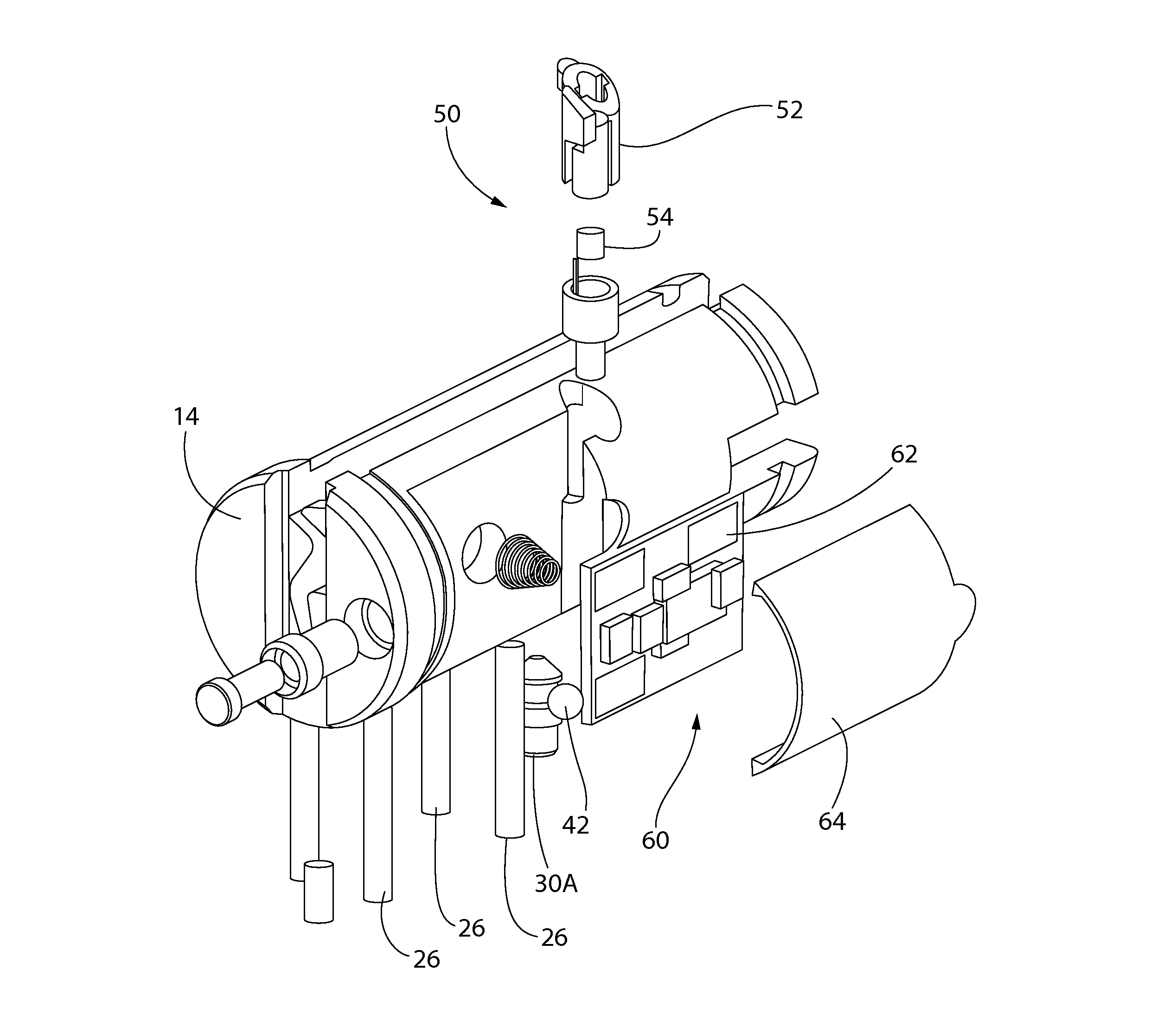
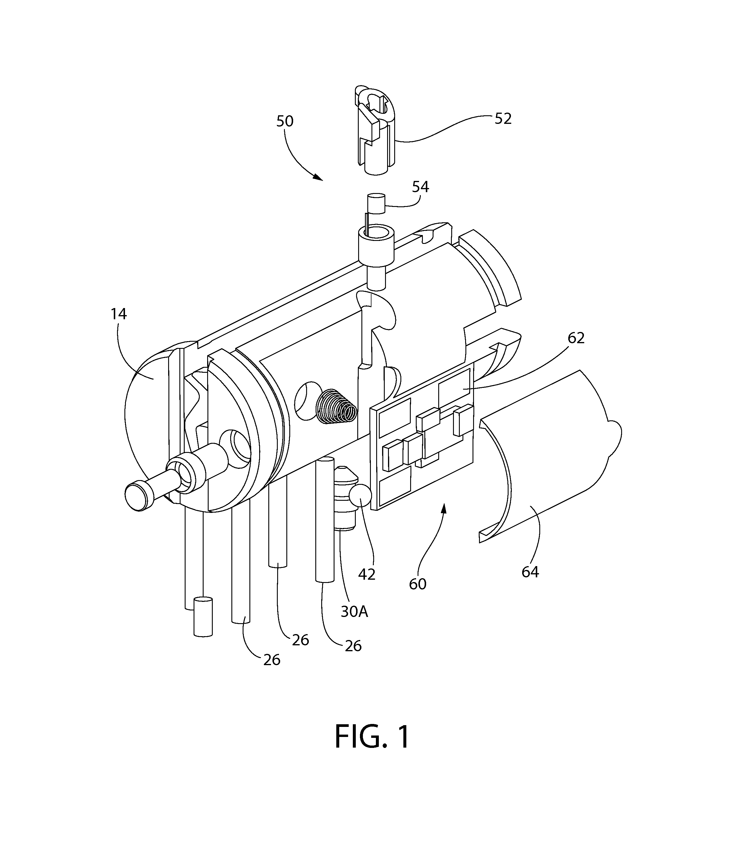
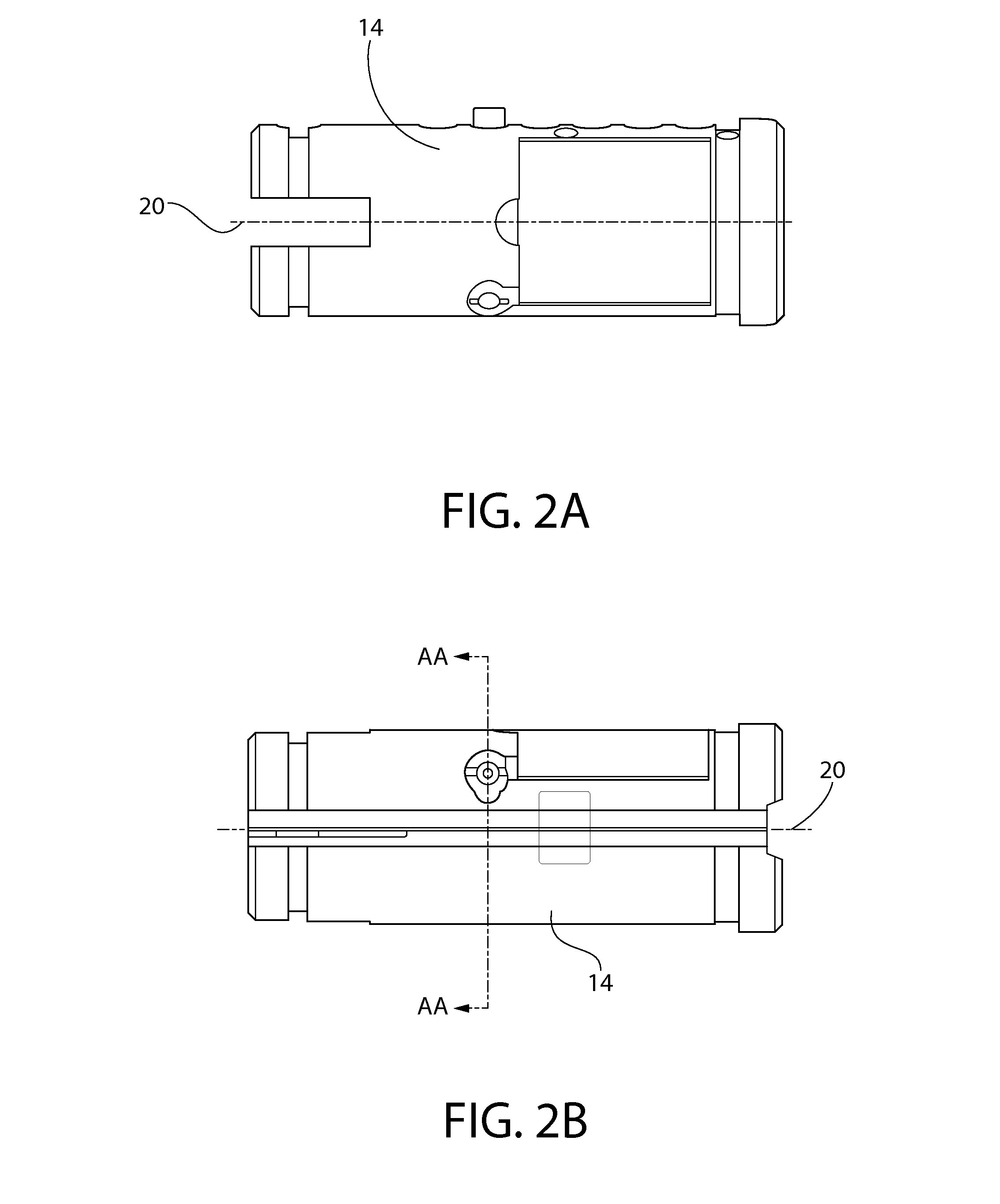
A locking device and system are disclosed. The locking device includes a barrel within which sets a plug. A plurality of pins sit in pin pathways that extend partially through the barrel and plug and the pins prevent rotation of the barrel within the plug when the ends of the pins are not aligned with a shear line. One of the pins has a recess formed therein within which a locking ball can sit. The engagement or otherwise of the locking ball in the recess is controlled by a linear actuator. When the linear actuator allows the locking ball to disengage the recess the pin with the recess in can engage the key and a line the end of the pin with the shear line.

Description

CROSS-REFERENCE TO RELATED APPLICATIONS[0001]This application claims priority under 35 U.S.C. §119 to United Kingdom Patent Application No. 1412734.4, filed Jul. 17, 2014, the entirety of which is hereby incorporated herein by reference.FIELD OF THE INVENTION[0002]The present invention relates to a locking device and relates particularly, but not exclusively, to an electronic and mechanical locking device for use replacing a standard cylinder lock.BACKGROUND OF THE INVENTION[0003]Electronically encoding a digital password into a key is a well-known technique for enhancing the security of a mechanical locking device. However, such electronic security requires electrical power which must be supplied to both the key and the cylinder. The electronic components in the cylinder lock generally control a solenoid and significantly more power is required to activate this solenoid than is needed to power the key. As a result, the batteries that are needed for the cylinder are either prone to ...

Claims


Application Information

Patent Timeline
Patent Type & Authority Applications(United States)
IPC IPC(8): E05B27/00E05B19/26E05B47/00E05B49/00
CPCE05B27/0003E05B19/26E05B47/0002E05B2047/0072E05B49/00E05B2047/0067E05B47/0038E05B47/0044E05B47/063E05B47/0626
Inventor CHARNLEY, JOHNSHEPPARD, CLINTONGREEN, GLYN
Owner HENRY SQUIRE & SONS
Learn More