Sun-tracking photovoltaic power generation system

Inactive Publication Date: 2016-01-21
ELM CO LTD
View PDF4 Cites 12 Cited by
  • Summary
  • Abstract
  • Description
  • Claims
  • Application Information

AI Technical Summary

Benefits of technology

[0014]According to the above configuration, the plurality of rails are provided on the undersurface of the base having the plurality of photovoltaic power generation panels loaded thereon, and the wheels on which the rails are placed are provided on a top surface of the stand at an installation site. As a result, it is easier to car

Problems solved by technology

As a result, the foregoing photovoltaic power generation system is currently used only for small-scale power generation with limited installation area such as on a roof of a building.
However, because the system is large, the rail has to be raid over a large area, and it is difficul

Method used


Image

  • Sun-tracking photovoltaic power generation system
  • Sun-tracking photovoltaic power generation system
  • Sun-tracking photovoltaic power generation system

Examples


Embodiment Construction

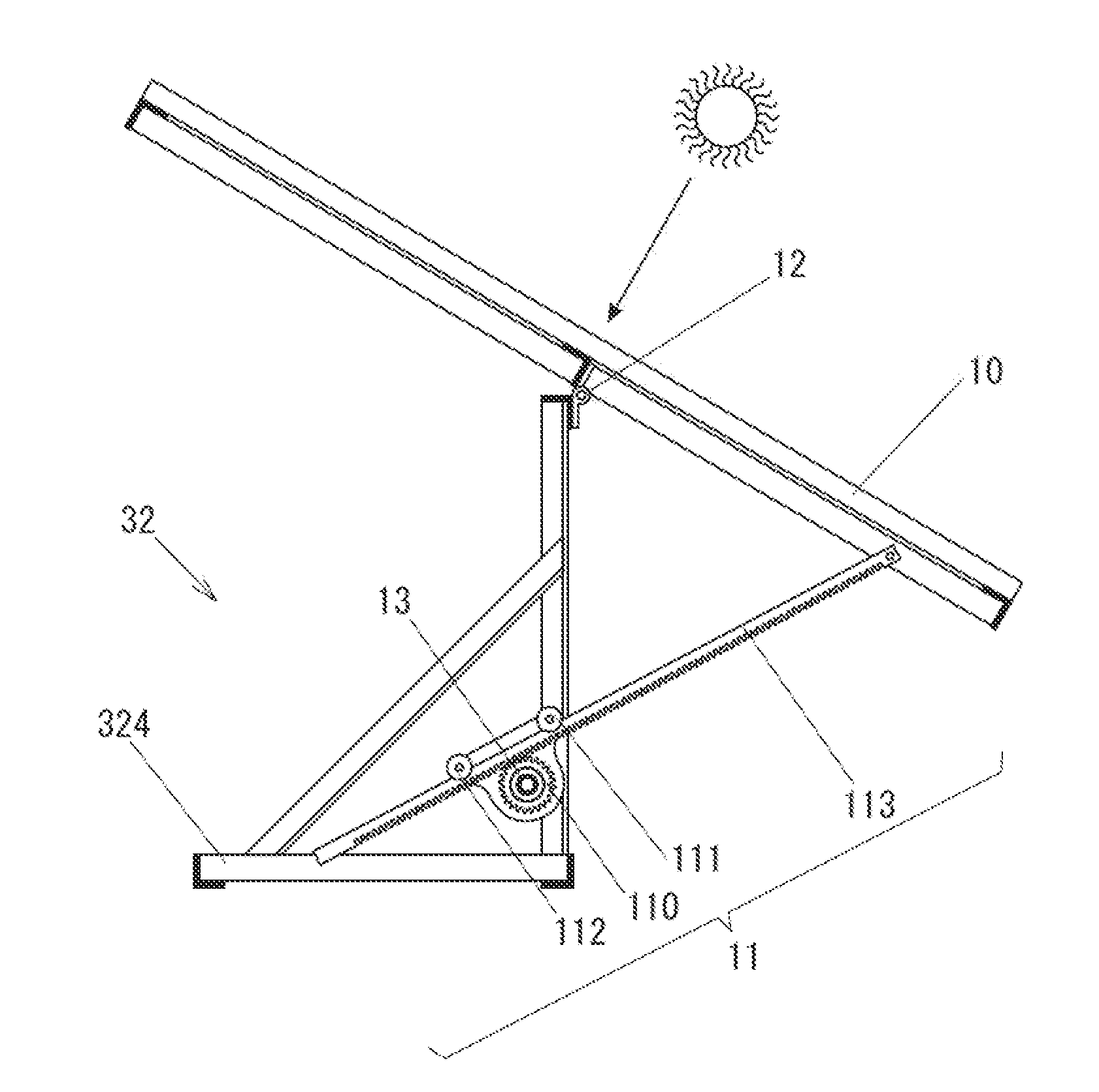
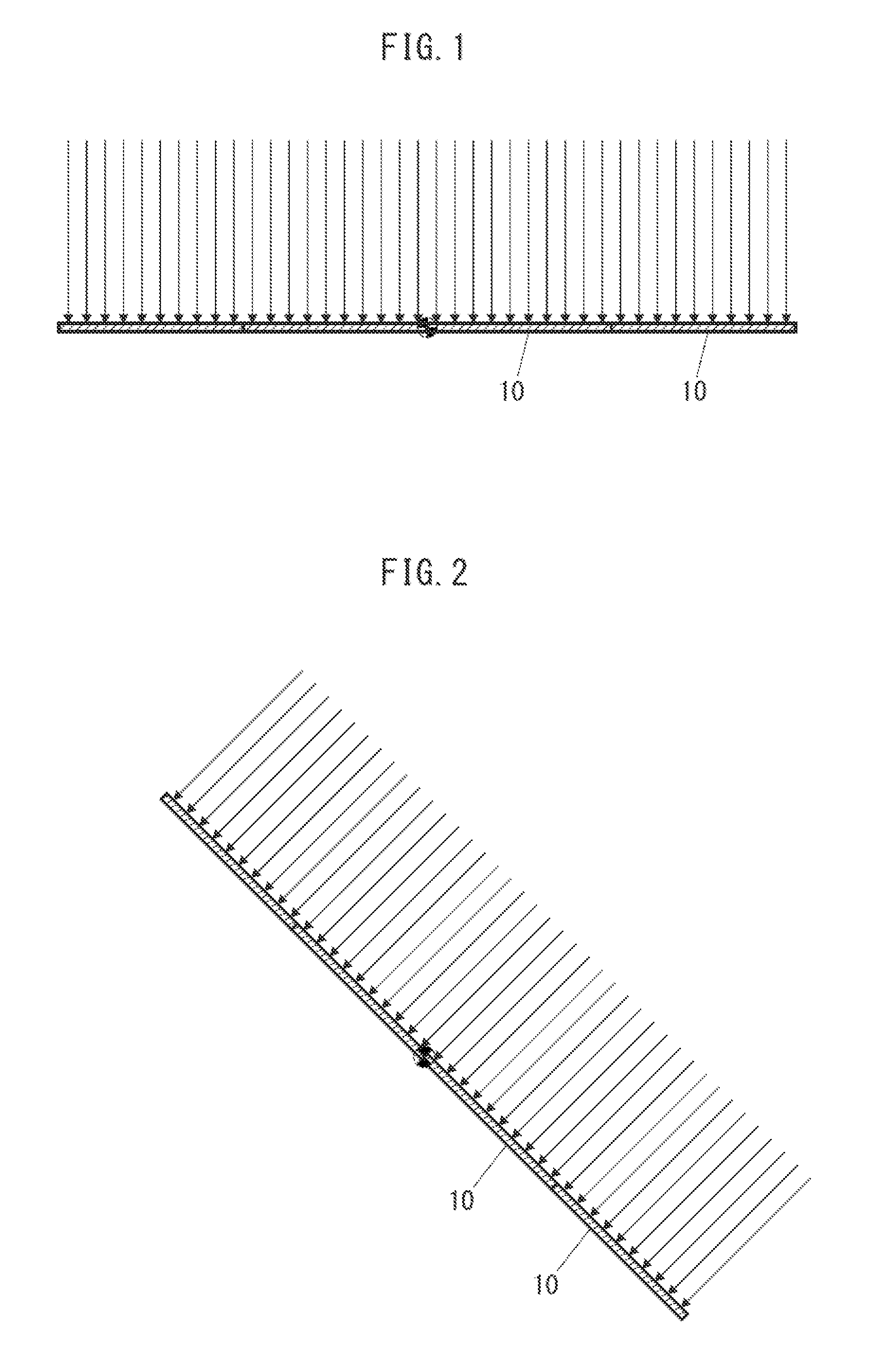
[0036]A sun-tracking photovoltaic power generation system according to the present invention is configured to move a base having a plurality of photovoltaic power generation panels 10 closely loaded thereon such that the panels 10 are directly opposite to the sun, as shown in FIG. 1. Accordingly, even when the solar azimuth changes, the energy of the sunlight emitted to surfaces of the photovoltaic power generation panels 10 efficiently enters the panels 10 by the panels 10 tracking the sun such that the panels 10 and the sun are directly opposite to each other as shown in FIG. 2. Further, because the photovoltaic power generation panels 10 can be closely loaded, the power generation amount per unit area can be improved significantly.

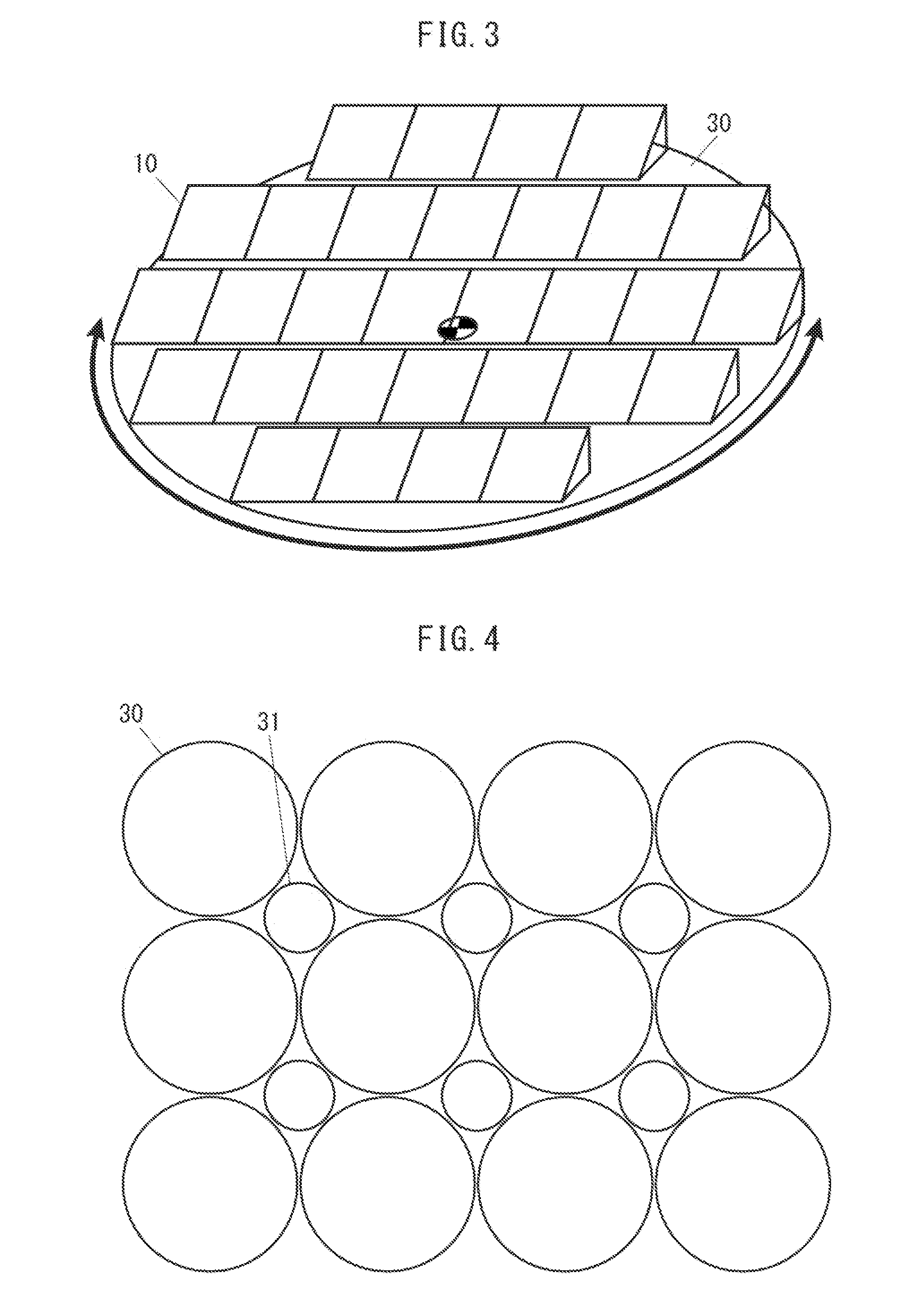
[0037]Hereinafter, an embodiment of the sun-tracking photovoltaic power generation system according to the present invention will be shown in FIG. 3 and the configuration and the operational effects will be described. As shown in FIG. 3, the photovoltai...


PUM


Abstract

A sun-tracking photovoltaic power generation system with a rotating a base having a plurality of photovoltaic power generation panels loaded thereon closely to each other following changes in the solar azimuth angle. A plurality of rails are concentrically laid on an undersurface of the base and wheels are provided to a stand closer to the ground. As a result, it is easier to support the wheels on the same horizontal plane than laying the rails horizontally on a large installation space. Therefore, the construction cost can be reduced and the construction period can be shortened, thereby achieving a large sun-tracking photovoltaic power generation system. Also, because the base is concentrically reinforced by the plurality of rails, the base can be formed by combining, for example, metal L angles, so that a base with a large area can be made light weight at a low cost.

Description

TECHNICAL FIELD[0001]The present invention relates to a photovoltaic power generation system, and particularly relates to one tracking the azimuth (east-west) movement of the sun.BACKGROUND ART[0002]In recent years, there has been a growing need for new power sources using renewable energy in order to reduce CO2 emissions, discourage nuclear power generation, and the like. Among such new power sources, photovoltaic power generation is attracting attention for the improved electric generation efficiency and the reduced cost of a photovoltaic power generation panel. Photovoltaic power generation is performed by converting energy of sunlight entering a photovoltaic power generation panel to electric energy. The photoelectric conversion efficiency is shown by the ratio of electric energy which can be practically taken out from a photovoltaic power generation panel 10 relative to the energy of sunlight 20 perpendicularly entering the panel 10, as shown in FIG. 12A.[0003]When the electric...

Claims


Application Information

Patent Timeline
IPC IPC(8): H02S20/32
CPCH02S20/32Y02E10/47F24S2030/145F24S30/422F24S2030/134F24S2030/16F24S30/452Y02E10/50
Inventor MIYAHARA, TAKAKAZUMIYAHARA, TERUMASA
Owner ELM CO LTD
Why Eureka
Try Eureka