Efficiency-optimised high-frequency power amplifier

Active Publication Date: 2016-01-21
ROHDE & SCHWARZ GMBH & CO KG
View PDF3 Cites 4 Cited by
  • Summary
  • Abstract
  • Description
  • Claims
  • Application Information

AI Technical Summary

Benefits of technology

[0024]By preference, the first push-pull transistor and the second push-pull transistor are each arranged in their own housing

Problems solved by technology

In this context, a wide spacing of the first harmonic is also desirable at the same time, because, with just under one octave bandwidth, it is only possible to achieve required harmonic spacing with a filter connected downstream subject to considerable technical effort.
In this context, the narrow bandwidth of approximately 10-15% in each case, which necessitates an effort-intensive frequency re-tuning in order to cover a relatively larger frequency range, is disadvanta

Method used


Image

  • Efficiency-optimised high-frequency power amplifier
  • Efficiency-optimised high-frequency power amplifier
  • Efficiency-optimised high-frequency power amplifier

Examples


Example

DETAILED DESCRIPTION OF THE DRAWINGS

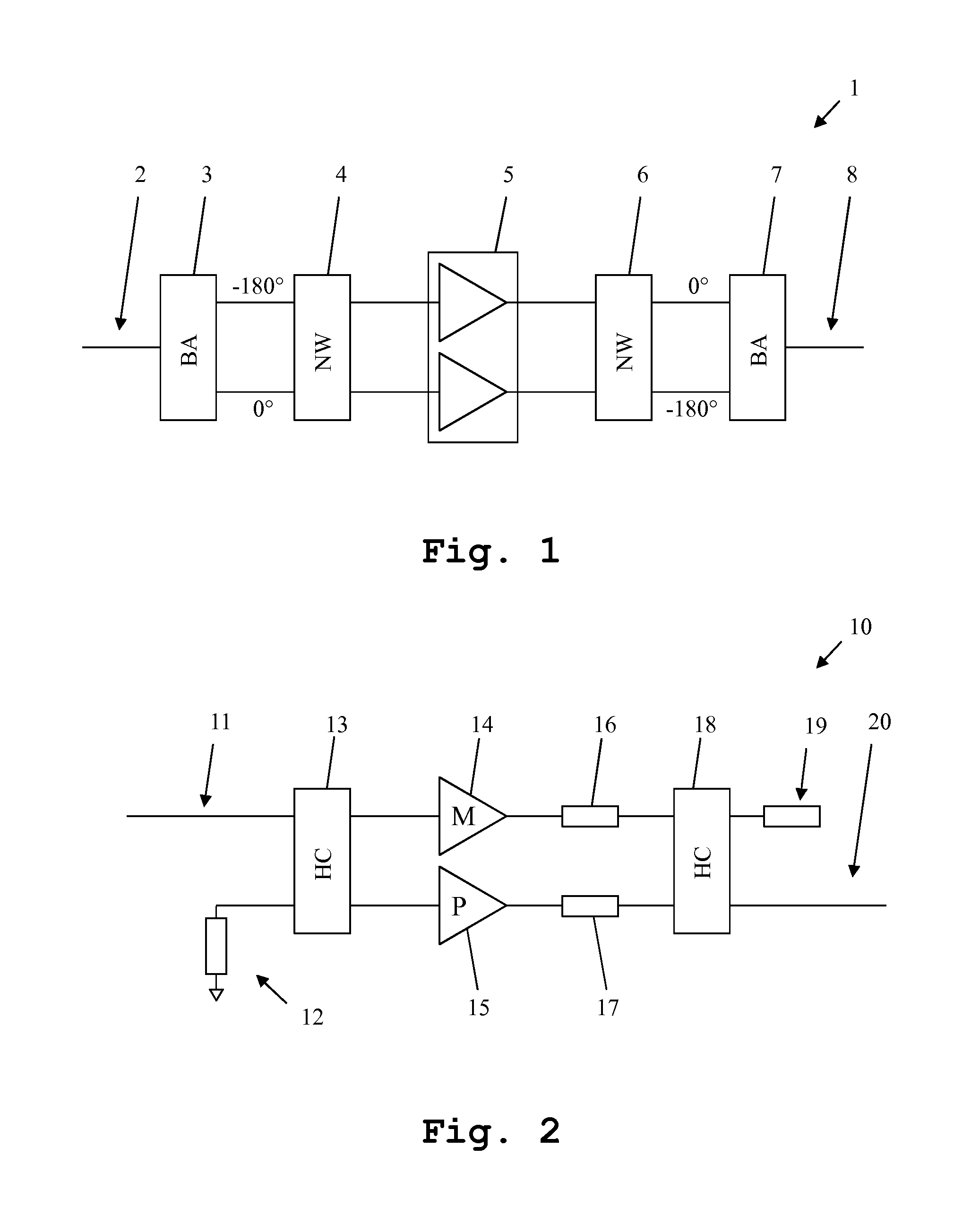
[0033]Since the relevant prior art has already been described with reference to FIG. 1 and FIG. 2, different exemplary embodiments of the amplifier according to the invention will be described and their function explained with reference to FIGS. 3-7. In some cases, the presentation and description of identical elements in similar drawings has not been repeated.

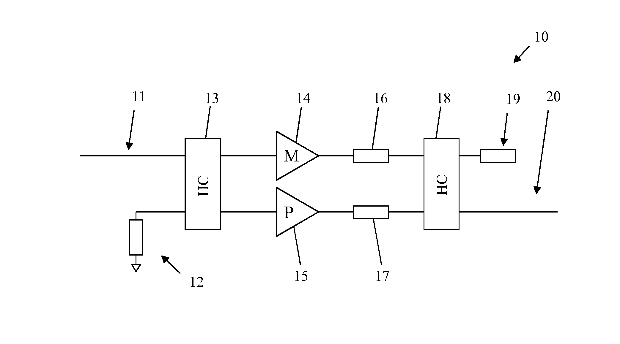
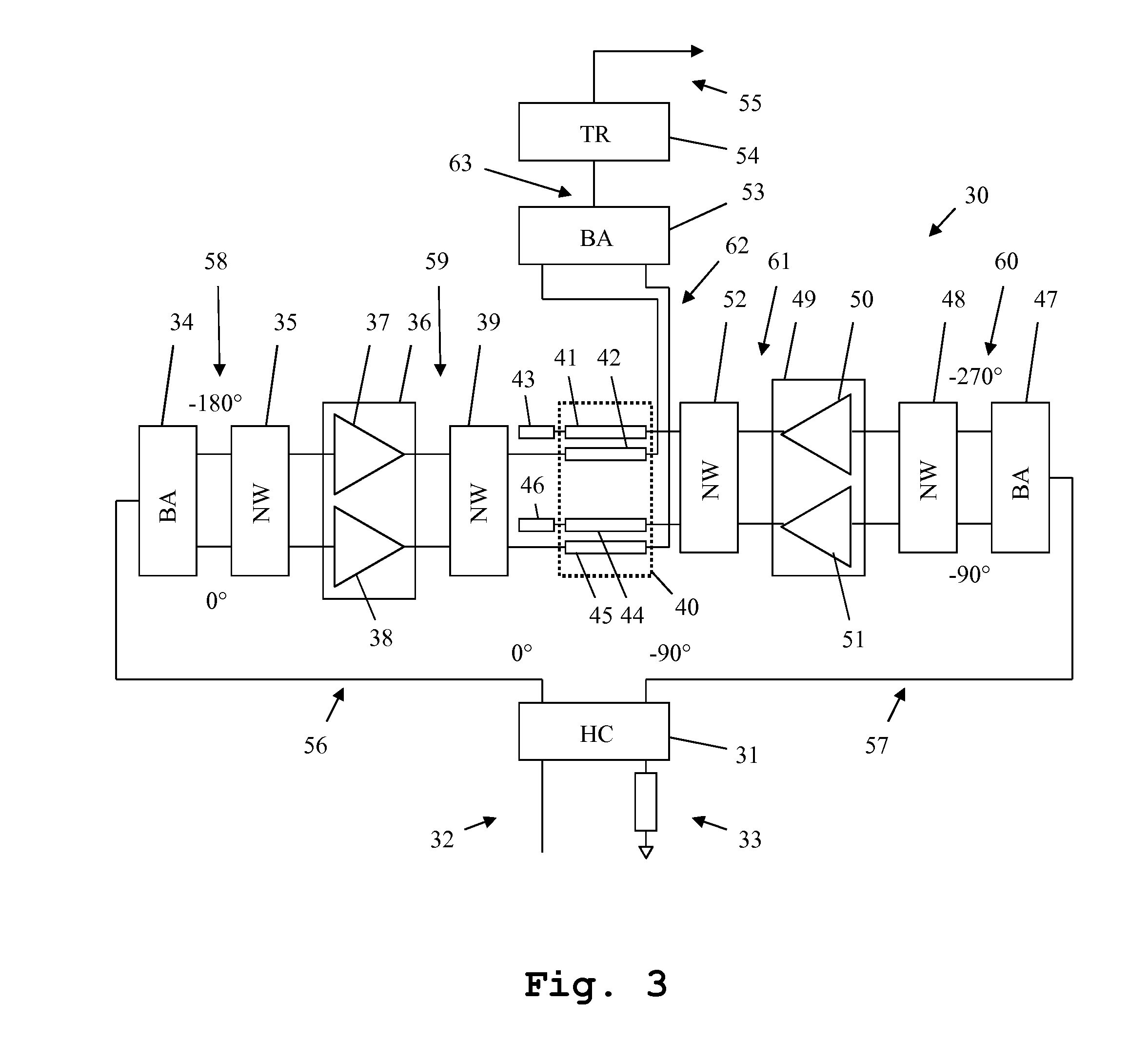
[0034]FIG. 3 shows a first exemplary embodiment of the amplifier 30 according to the invention. The amplifier 30 according to the invention accordingly provides a hybrid coupler 31 which is supplied with an unbalanced input signal 32 at a first input terminal and terminated with a load-balancing resistor 33 at a second input terminal. The unbalanced input signal 32 is split by the hybrid coupler 31 into an unbalanced auxiliary-amplifier input signal 56 and an unbalanced main-amplifier input signal 57. In this context, a 90° phase offset exists between the signals 56, 57.

[0035]The auxiliary-a...


PUM


Abstract

An amplifier according to the principle of load modulation comprises a first push-pull transistor, a second push-pull transistor and a balanced hybrid coupler. The first push-pull transistor is configured as a main amplifier and generates a balanced main-amplifier signal. The second push-pull transistor is configured as an auxiliary amplifier and generates a balanced auxiliary-amplifier signal. Outputs of the first push-pull transistor and of the second push-pull transistor are connected to the balanced hybrid coupler in such a manner that the balanced hybrid coupler combines the main-amplifier signal and the auxiliary amplifier signal according to the principle of load modulation to form a balanced output signal.

Description

CROSS-REFERENCE TO RELATED APPLICATION[0001]This application claims priority of German patent application DE 10 2014 213 684.9 filed on Jul. 15, 2014.FIELD OF THE INVENTION[0002]The invention relates to a high-frequency power amplifier which operates internally with a balanced signal and operates in a similar manner to a Doherty amplifier on the principle of load modulation.BACKGROUND OF THE INVENTION[0003]Since high-frequency power amplifiers in transmission units, especially in base stations or radio and television transmitters, participate significantly in the energy consumption of the overall unit and accordingly directly influence operating costs, their level of efficiency is a substantial feature. To achieve large signal bandwidths or to allow a rapid frequency change, the high-frequency bandwidth of the amplifier is also an important criterion. In this context, a wide spacing of the first harmonic is also desirable at the same time, because, with just under one octave bandwid...

Claims


Application Information

Patent Timeline
IPC IPC(8): H03F1/02H03F3/21H03F3/26H03F3/19
CPCH03F1/0288H03F3/19H03F3/211H03F3/26H03F2203/21106H03F2200/451H03F3/245H03F3/602H03F2200/192H01P5/187
Inventor KAEHS, BERNHARD
Owner ROHDE & SCHWARZ GMBH & CO KG
Why Eureka
Try Eureka