Friction plate and wet-type multiple-disc clutch with friction plate

a technology of friction plate and wet-type multiple-disc clutch, which is applied in the direction of mechanical actuated clutches, friction linings, couplings, etc., can solve the problems of reducing the drag torque, power loss through a lubricant, and reducing the drag, so as to avoid the reduction of the area of the friction member, reduce the drag torque, and prevent the degradation of heat resistance and durability.

Active Publication Date: 2016-01-28
NSK WARNER
View PDF1 Cites 7 Cited by
  • Summary
  • Abstract
  • Description
  • Claims
  • Application Information

AI Technical Summary

Benefits of technology

[0011]In consideration of the above-described problems, the present invention aims to provide a friction plate in which a drag torque is able to be reduced at a low rotation speed range, and degradation of heat resistance and durability is prevented by providing minute grooves for avoiding reduction of the area of a friction member in the friction plate of a wet-type multiple-disc clutch.

Problems solved by technology

In such a wet-type multiple-disc clutch, there is an occurrence of drag torque leading to a power loss through a lubricant at the time of disengagement of the clutch.
Hence, recently, reduction of the drag torque has become a major challenge for automatic transmissions to be compliant with the demand for environmental regulation and low fuel consumption in vehicles.
While reduction of the drag torque has been highly demanded at the variable rotation speed range, particularly at a low rotation speed range, the countermeasures in the related art have problems described below.
However, if the area of the groove for draining oil is increased in order to acquire a better reduction effect, the friction area in the friction plate decreases, thereby resulting in a problem of degradation of heat resistance and durability.
However, if the shape of the segment is utilized in order to improve the oil drainage in pursuing a better reduction effect, it is not possible for a lubricant to stably form an oil film on the surface of the friction member, thereby causing fluid shearing resistance hindering the reduction of the drag torque.

Method used


Image

  • Friction plate and wet-type multiple-disc clutch with friction plate
  • Friction plate and wet-type multiple-disc clutch with friction plate
  • Friction plate and wet-type multiple-disc clutch with friction plate

Examples


first embodiment

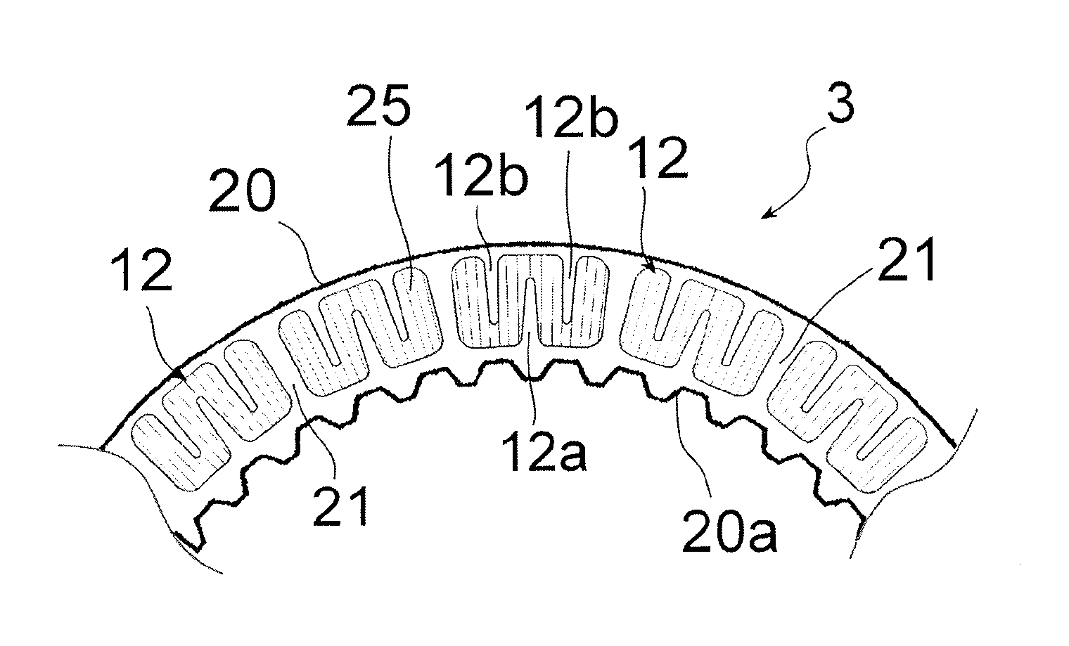
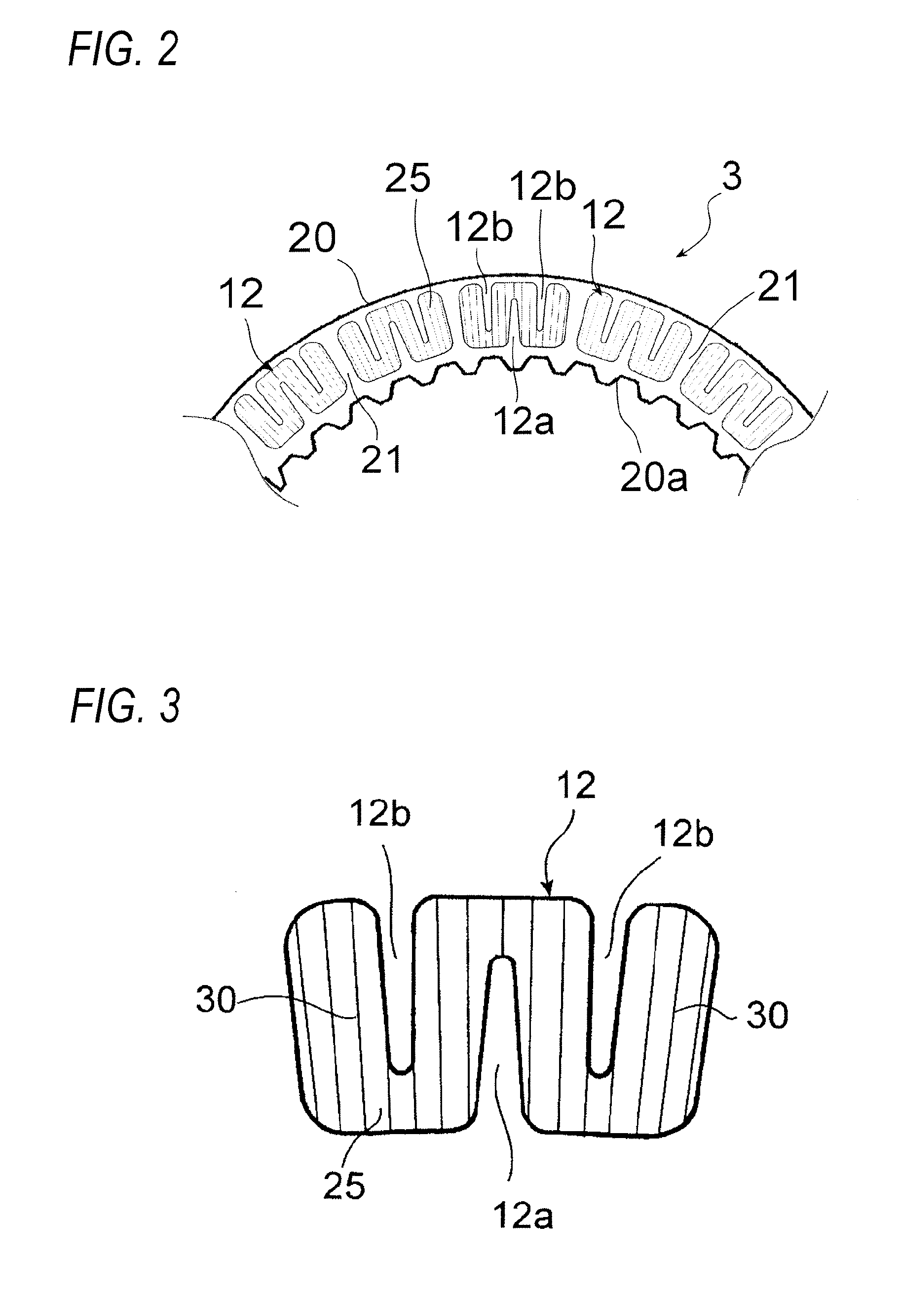
[0034]FIG. 2 is a partial front view of a friction plate 3 illustrating a first embodiment of the present invention. The friction plate 3 has a friction surface 25 formed by annularly fixing a plurality of the identical friction material segments 12 onto a surface of a substantially annular core plate 20 in the axial direction by using an adhesive or the like. A spline 20a which engages with a spline 5 of the hub 4 is provided on the inner periphery of the core plate 20. FIG. 2 illustrates the friction plate 3 partially, but the friction material segments 12 are annularly fixed to the core plate 20 at equal intervals and in the omitted portion as well, in a similar manner as that illustrated in FIG. 2.

[0035]An oil passage 21 which penetrates from the inner diameter to the outer diameter is defined between the friction material segment 12 and the friction material segment 12. Thus, the friction material segments 12 and the oil passages 21 are alternately disposed in a circumferential...

second embodiment

[0044]FIG. 4 is a front view of an alternate friction material segment 12 which is used in the friction plate of a second embodiment of the present invention. According to the second embodiment, the extending direction of the minute groove formed on the friction surface 25 of the friction material segment 12 is different from that in the first embodiment.

[0045]In the second embodiment, a plurality of minute grooves 40 are provided in the friction material segment 12 at equal intervals in the circumferential direction. As is clear in FIG. 4, the minute grooves 40 extend from one end to the other end of the friction material segment 12 in the circumferential direction.

[0046]In the second embodiment as well, the width and the depth of each minute groove 40, and the area ratio thereof with respect to the friction surface 25 are set similarly to the case of the first embodiment.

third embodiment

[0047]FIG. 5 is a front view of another alternate friction material segment 12 which is used in the friction plate of a third embodiment of the present invention. The third embodiment is constituted of a combination of the first embodiment and the second embodiment. The minute grooves 30 extending in the radial direction and the minute grooves 40 extending in the circumferential direction are formed on the friction surface 25 of the friction material segment 12.

[0048]According to the third embodiment, since the minute grooves 30 extending in the radial direction at equal intervals and the minute grooves 40 extending in the circumferential direction at equal intervals are formed, the area ratio with respect to the friction surface 25 is higher than those in the first embodiment and the second embodiment. However, a surface oil film is able to be ensured between the friction plate 3 and the separator plate 2. Therefore, fluid shearing resistance is able to be reduced.

[0049]As is clear...


PUM


Abstract

A friction plate is formed by annularly fixing a plurality of friction material segments to a substantially annular core plate, and a minute groove is formed on a surface of the friction material segment.

Description

BACKGROUND OF THE INVENTION[0001]1. Field of the Invention[0002]The present invention relates to a friction plate used in a clutch or a brake of an automatic transmission in vehicles, and a wet-type multiple-disc clutch provided with the friction plate.[0003]2. Description of the Related Art[0004]In general, a wet-type multiple-disc clutch in an automatic transmission has friction plates and separator plates, which are alternately disposed between the drum and the hub of the clutch or a brake, and the clutch is engaged and disengaged by pressing and releasing a clutch piston.[0005]In such a wet-type multiple-disc clutch, there is an occurrence of drag torque leading to a power loss through a lubricant at the time of disengagement of the clutch. Hence, recently, reduction of the drag torque has become a major challenge for automatic transmissions to be compliant with the demand for environmental regulation and low fuel consumption in vehicles.[0006]As a technique in the related art f...

Claims


Application Information

Patent Timeline
Patent Type & Authority Applications(United States)
IPC IPC(8): F16D13/74F16D13/52F16D13/64
CPCF16D13/74F16D13/648F16D13/52F16D25/0638F16D25/123F16D2069/004F16D2300/10F16D65/127
Inventor KOBAYASHI, MASATOMIYAZAKI, TOMOYUKINATSUMEDA, SHINICHI
Owner NSK WARNER
Why Eureka
Try Eureka