Light-emitting device and electronic apparatus

a technology of light-emitting devices and electronic devices, which is applied in the field of image display techniques, can solve the problems of difficult to obtain a sufficient amount of light transmitted through the first color filter, and complicated formation process of color filters and and achieve the effect of simplifying the formation process of color filters and the structure of light-emitting devices

Active Publication Date: 2016-01-28
SEIKO EPSON CORP
View PDF3 Cites 17 Cited by
  • Summary
  • Abstract
  • Description
  • Claims
  • Application Information

AI Technical Summary

Benefits of technology

[0005]In techniques in JP-A-2006-32010 and JP-A-2012-28058, since three types of color filters for different colors need to be formed separately, a formation process of color filters and a structure ...

Problems solved by technology

In techniques in JP-A-2006-32010 and JP-A-2012-28058, since three types of color filters for different colors need to be formed separately, a formation process of color filters and a structure of a light-emitting device are complicated.
If, for example, a spectrum of light emitted from the second light-emitting element and the third light-emitting element only cover...

Method used


Image

  • Light-emitting device and electronic apparatus
  • Light-emitting device and electronic apparatus
  • Light-emitting device and electronic apparatus

Examples


embodiment 1

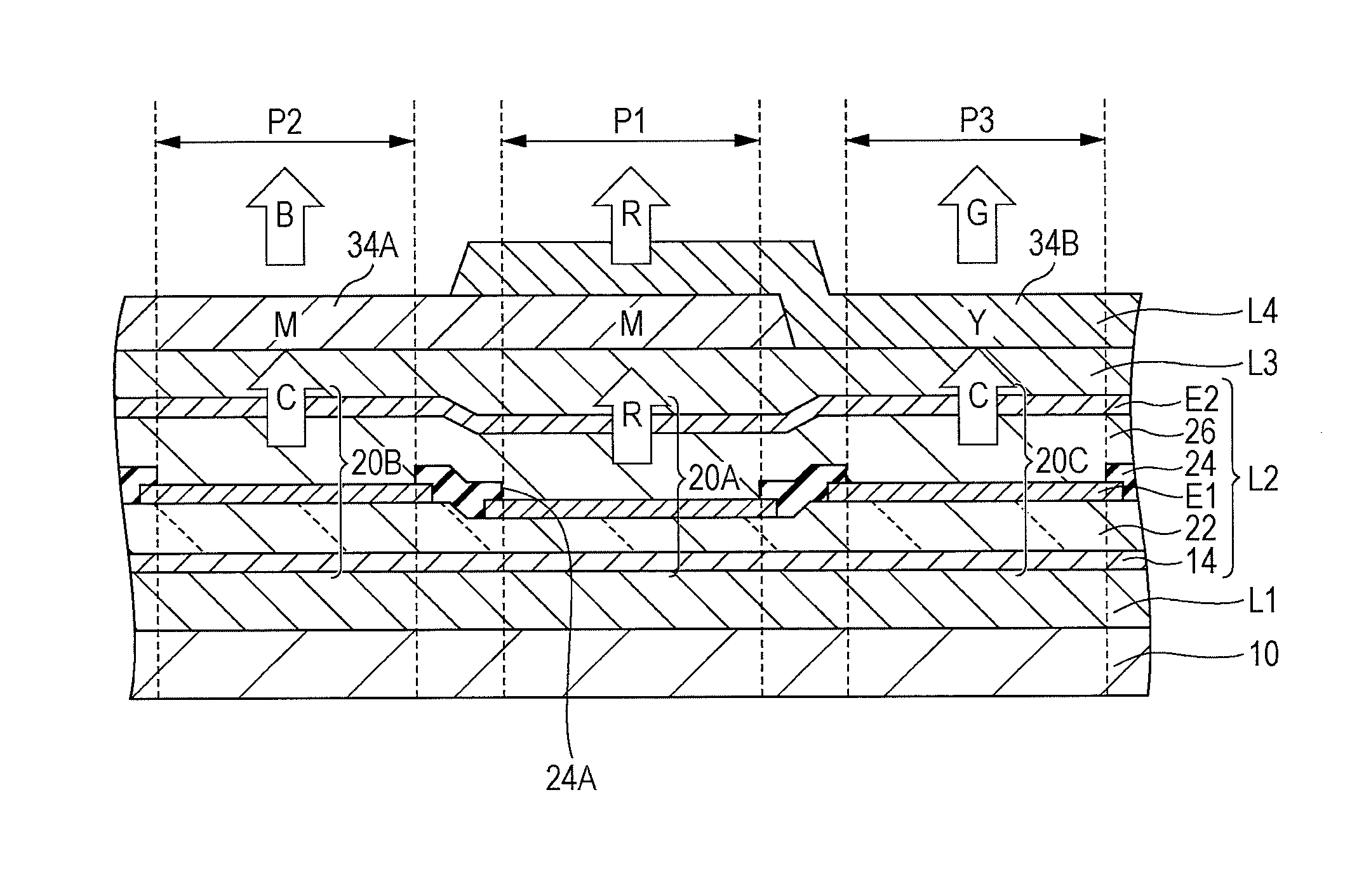
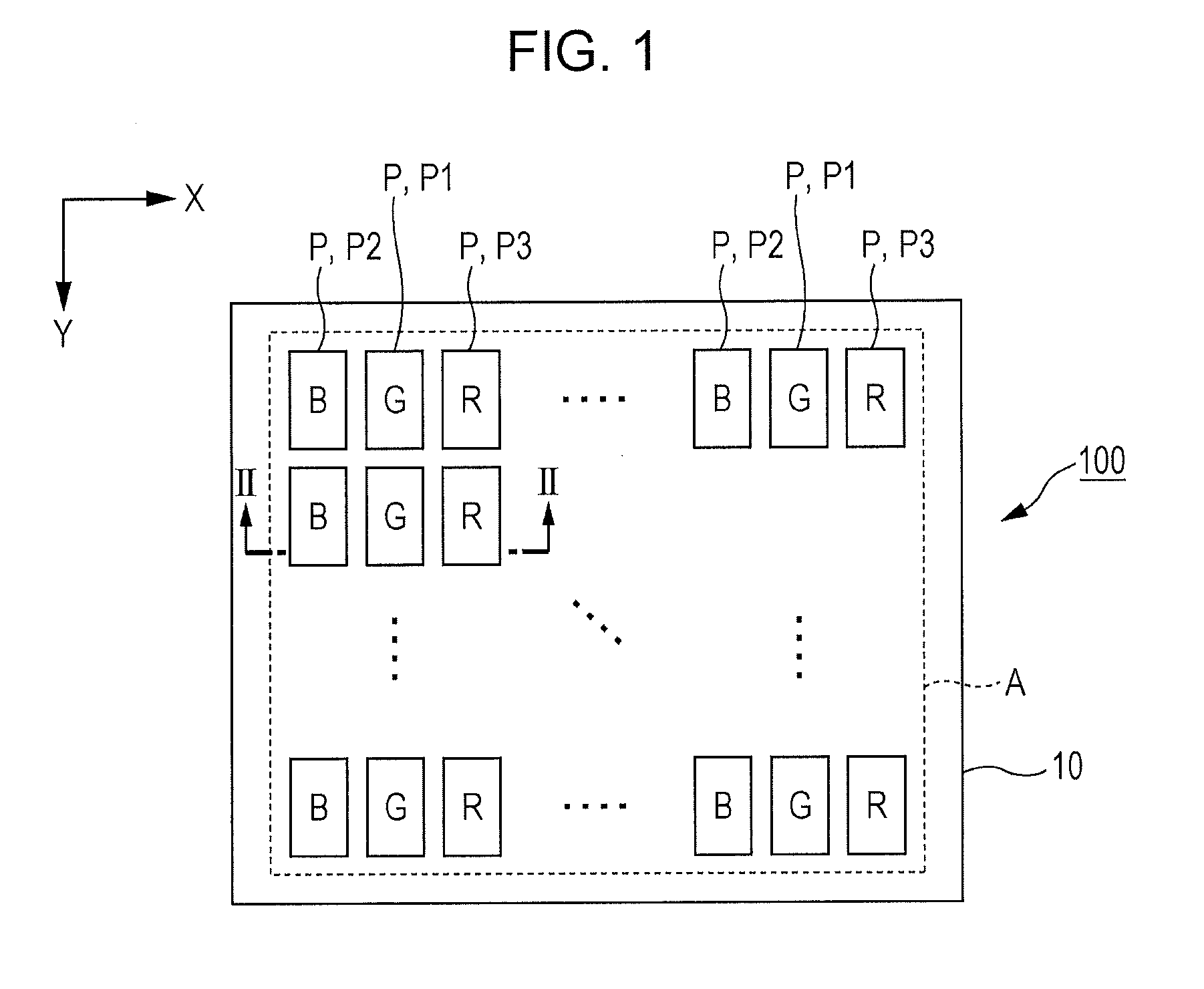
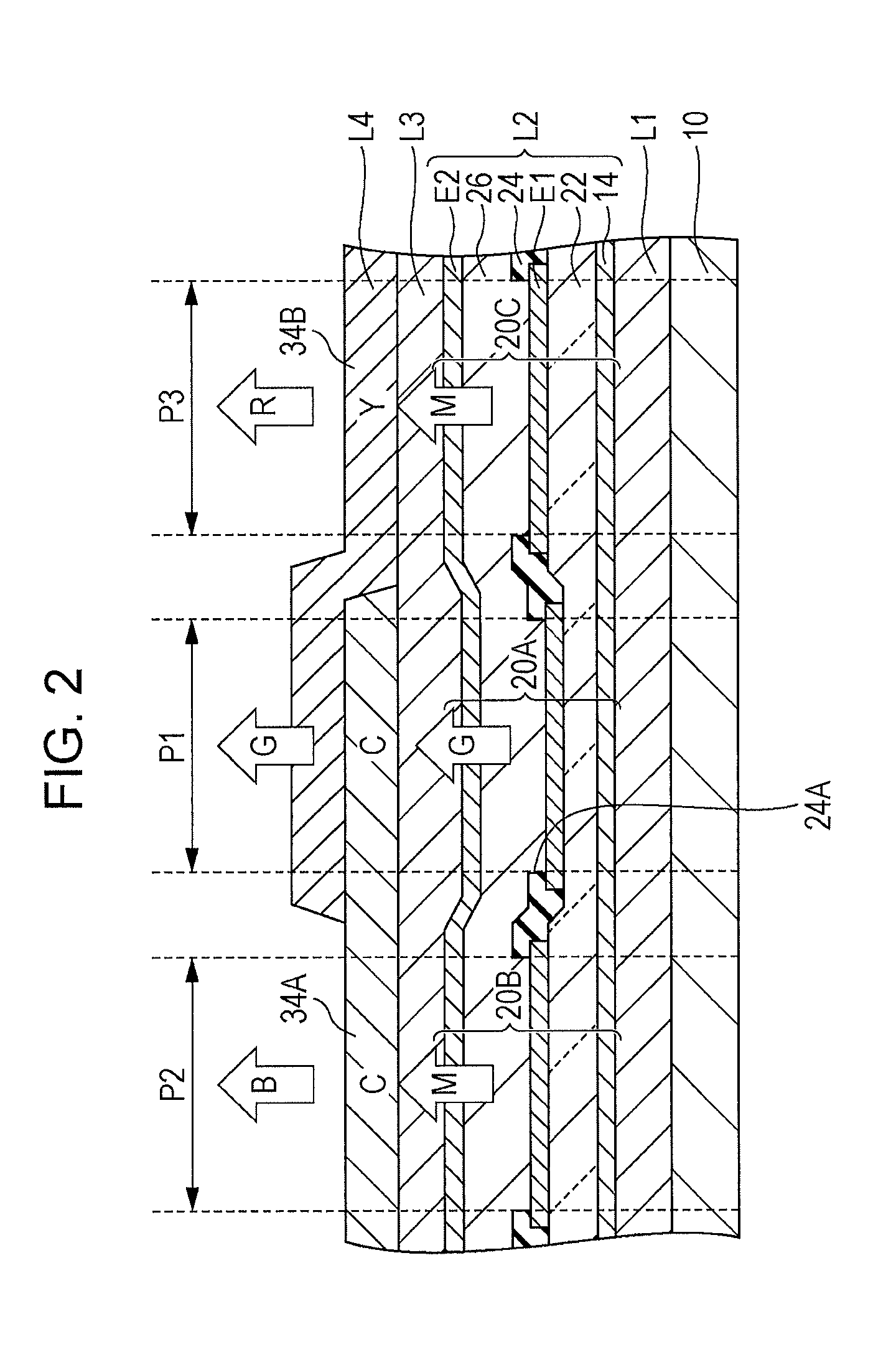
[0032]FIG. 1 is a plan view illustrating a light-emitting device 100 according to Embodiment 1 of the invention. The light-emitting device 100 according to Embodiment 1 is an organic EL device in which a light-emitting element including an organic EL material is formed on a substrate 10. The light-emitting device 100 includes a display region A in which a plurality of pixels (sub-pixels) P are arranged in matrix along an X-direction and Y-direction which intersect with each other. The pixels P in the display region A include three types of pixels P (P1, P2, and P3) for different display colors. Specifically, a pixel P1 emits light of a medium wavelength range which corresponds to a green (G) color, a pixel P2 emits light of a short wavelength range which corresponds to a blue (B) color, and a pixel P3 emits light of a long wavelength range which corresponds to a red (R) color. The pixel P1, the pixel P2, and the pixel P3 form one dot of a display image. A drive circuit (not illustra...

embodiment 2

[0054]Embodiment 2 of the invention is now described. In Embodiment 1, emission light from the second light-emitting element 20B and the third light-emitting element 20C are generated by a resonance structure in which resonance of a resonance wavelength in the second wavelength range Q2 and resonance of a resonance wavelength in the third wavelength range Q3 occur in parallel. In Embodiment 2, light with a spectrum having a single peak covering the second wavelength range Q2 and the third wavelength range Q3 is emitted from the second light-emitting element 20B and the third light-emitting element 20C. Note that in the following examples, with regard to elements having a similar effect or function to those of Embodiments 1, reference numerals in Embodiment 1 are used and detailed description of such elements is omitted as appropriate.

[0055]FIG. 5 is a cross-sectional view of the light-emitting device 100 according to Embodiment 2. FIG. 6 illustrates spectral characteristics of light...

modification example a

[0067]FIG. 8 is a cross-sectional view of the light-emitting device 100 according to Modification Example A. As illustrated in a plan view of FIG. 8, a partition 36 is formed between the first color filter 34A and the second color filter 34B, in a region between the pixel P2 and the pixel P3. In a structure of FIG. 8, the partition 36 separates the first color filter 34A and the second color filter 34B between the pixel P2 and the pixel P3, whereby overlapping of the first color filter 34A and the third light-emitting element 20C and overlapping of the second color filter 34B and the second light-emitting element 20B can be prevented.


PUM


Abstract

A light-emitting device includes a first pixel, a second pixel, and a third pixel. The first pixel includes a first light-emitting element that emits light in a first wavelength range. The second pixel includes a second light-emitting element that emits light in a fourth wavelength range that is different from the first wavelength range and that includes a second wavelength range and a third wavelength range and a first color filter that transmits light in the second wavelength range emitted from the second light-emitting element. The third pixel includes a third light-emitting element that emits light in the fourth wavelength range and a second color filter that transmits light in the third wavelength range emitted from the third light-emitting element.

Description

BACKGROUND[0001]1. Technical Field[0002]The present invention relates to a technique for displaying images using a light-emitting element such as an organic EL element.[0003]2. Related Art[0004]Light-emitting devices which display color images using light-emitting elements and color filters have been proposed. For example, JP-A-2006-32010 discloses a structure in which color filters of RGB colors (red, green, and blue) are formed for white light-emitting elements to display color images. JP-A-2012-28058 discloses a structure for generating three colors of RGB by a combination of three types of light-emitting elements emitting colors of RGB and three types of color filters which transmit respective colors of CMY (cyan, magenta, and yellow).SUMMARY[0005]In techniques in JP-A-2006-32010 and JP-A-2012-28058, since three types of color filters for different colors need to be formed separately, a formation process of color filters and a structure of a light-emitting device are complicated...

Claims


Application Information

Patent Timeline
IPC IPC(8): F21V9/40
CPCF21Y2103/006F21V9/10H10K59/351H10K59/38H10K59/876H10K50/852
Inventor SHIRATORI, KOYA
Owner SEIKO EPSON CORP
Why Eureka
Try Eureka