
Measurement apparatus and measurement method

Inactive Publication Date: 2016-01-28
SONY CORP
View PDF5 Cites 11 Cited by
  • Summary
  • Abstract
  • Description
  • Claims
  • Application Information

AI Technical Summary

Benefits of technology

The technique in this patent prevents the formation of air bubbles in the flow channel.

Problems solved by technology

In actuality, however, it is extremely difficult to measure an impedance of the narrow tube section using a metal electrode.
This is because an impedance due to an electrical double layer capacitance generated on a metal surface inevitably exists.

Method used


Image

  • Measurement apparatus and measurement method
  • Measurement apparatus and measurement method
  • Measurement apparatus and measurement method

Examples


first embodiment

[0039][Measurement Apparatus ]

[0040](Structure of Measurement Apparatus)

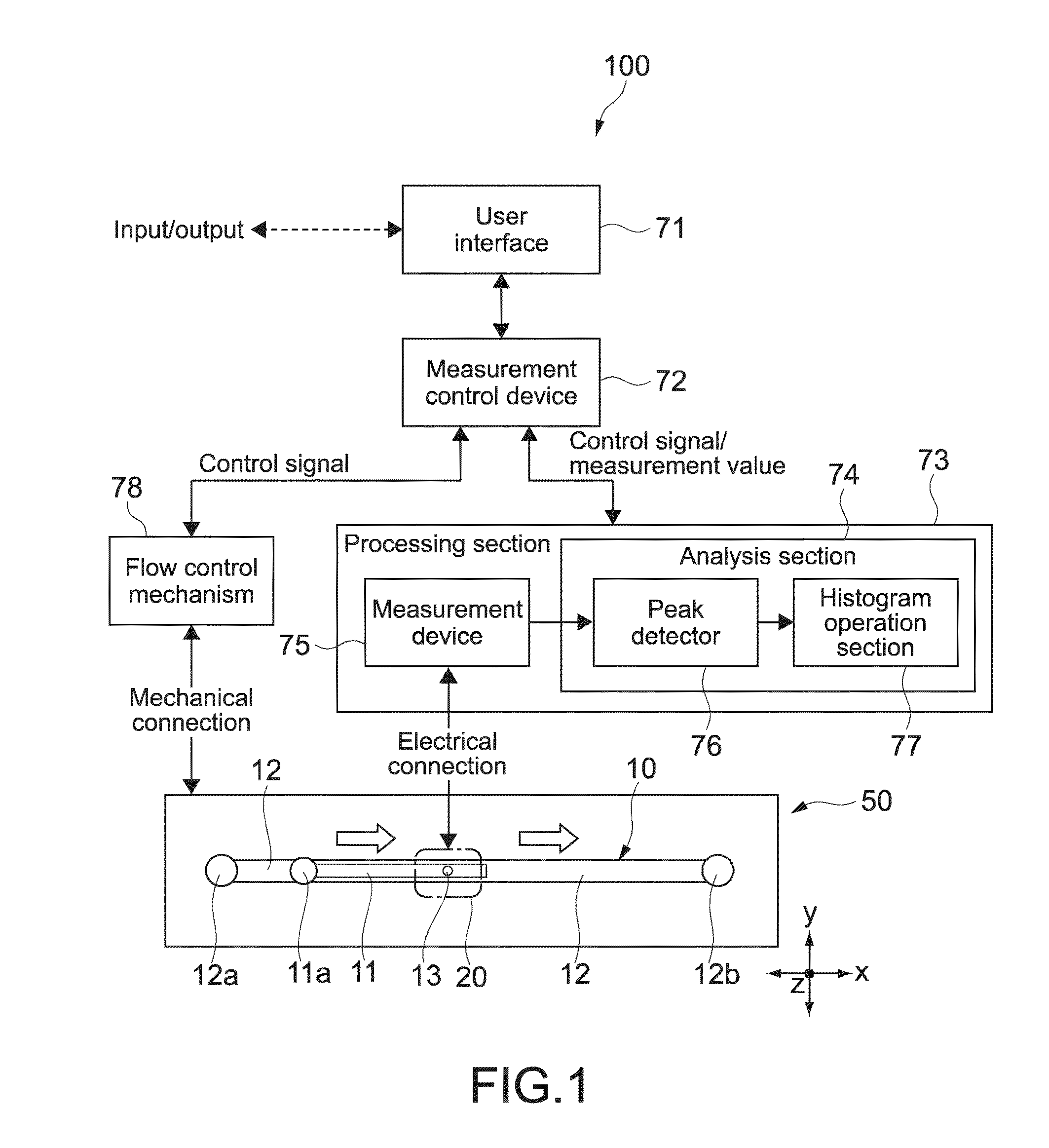
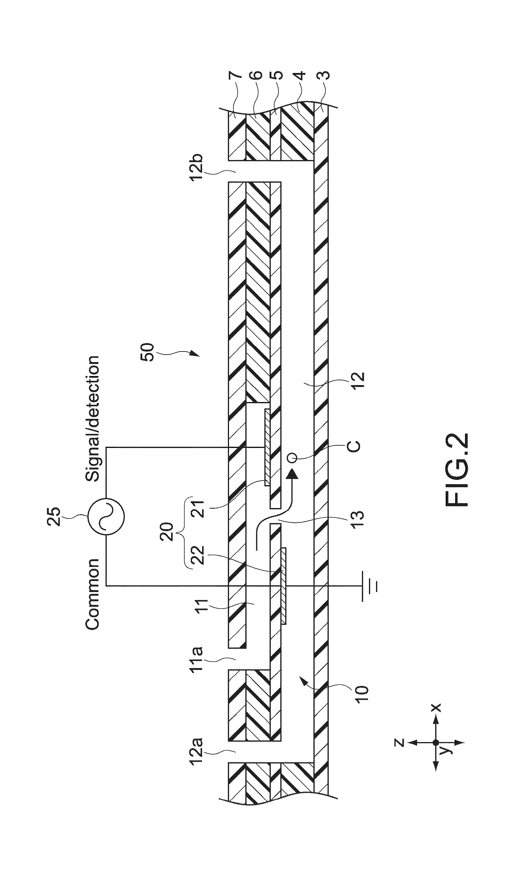
[0041]FIG. 1 is a block diagram showing a structure of a measurement apparatus according to a first embodiment of the present technique. The measurement apparatus 100 mainly includes a flow channel device 50, a processing section 73 electrically connected to the flow channel device 50, and a flow control mechanism 78 that controls a fluid of the flow channel device 50.

[0042]A user can input information to a measurement control device 72 using a user interface constituted of a keyboard, a mouse, a touch panel, and the like. The measurement control device 72 outputs a control signal corresponding to the input information to the processing section 73 or acquires a measurement value of an electrical amount to be described later or the like measured by the processing section 73 and other data. The measurement control device 72 may also output information output from the processing section 73 and the flow control mech...

second embodiment

[0117][Measurement Apparatus ]

[0118]FIG. 13 is a block diagram showing a structure of a measurement apparatus according to a second embodiment of the present technique. FIG. 14 is a cross-sectional diagram of a flow channel device 150 of the measurement apparatus 200 taken along the x direction. In the descriptions hereinafter, descriptions on members, functions, and the like that are the same as those of the measurement apparatus 100 of the embodiment shown in FIG. 1 and the like will be simplified or omitted, and different points will mainly be described.

[0119]The flow channel device 150 of the measurement apparatus 200 includes a branch section 15 that branches from a downstream edge of the second flow channel 12, an operation electrode section 40 provided immediately before the branch section 15, and a discharge flow channel 19 and a discharge port 18 provided on a downstream side of the branch section 15. The branch section 15 includes a plurality of, for example, two, branch c...


PUM


Abstract

A measurement apparatus includes a generation section and a measurement section and performs a predetermined measurement using a flow channel device including a narrow channel through which particles pass by a flow of a fluid and a measurement electrode section provided in the vicinity of the narrow channel. The generation section generates, in the measurement electrode section, an AC voltage that is higher than a characteristic frequency defined by a conductance of the fluid including the particles in the narrow channel and an electrical double layer capacitance formed by the measurement electrode section and has a frequency range indicating a conductance corresponding to a size of the particles. The measurement section measures, while the AC voltage is applied to the measurement electrode section, an electrical amount including at least the conductance obtained when the particles pass through the narrow channel.

Description

TECHNICAL FIELD[0001]The present technique relates to a measurement apparatus and a measurement method for measuring an electrical amount of particles such as blood cells.BACKGROUND ART[0002]In general, a counting apparatus for particles such as blood cells includes a flow channel including a narrow tube section such as an orifice and an aperture, and, when particles pass through the narrow tube section, an impedance of the narrow tube section changes according to an area blocked by the particles themselves. The counting apparatus detects the impedance change of the narrow tube section by causing a DC electricity to flow between electrodes respectively provided on an inlet side and outlet side of the narrow tube section in the flow channel, to thus measure the number of particles.[0003]In actuality, however, it is extremely difficult to measure an impedance of the narrow tube section using a metal electrode. This is because an impedance due to an electrical double layer capacitance ...

Claims


Application Information

Patent Timeline
IPC IPC(8): G01N15/12G01N15/02
CPCG01N15/1209G01N2015/0065G01N15/0266G01N15/1031G01N15/1023G01N2015/1028G01N15/132G01N15/01G01N15/131
Inventor KATSUMOTO, YOICHISATO, KAZUMASABRUN, MARCAURELE
Owner SONY CORP
Learn More